Application guide by addaScanCompare the inspection task, imaging conditions and validation steps with your own production line.
- Task
- Automotive glue-bead inspection
- Decision focus
- Bead inspection
- Workflow
- Anchor the bead route to stable datums.
- Validation
- Good bead variation at corners
Glue-bead continuity, width and path position
Original explanatory diagrams show the product states and inspection questions. They are schematics, not captured inspection results.
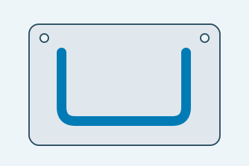
The bead follows the intended route.
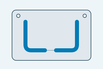
A gap breaks required continuity.
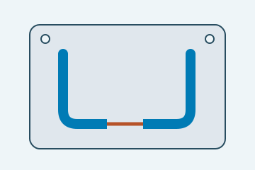
A section differs from the allowed width.
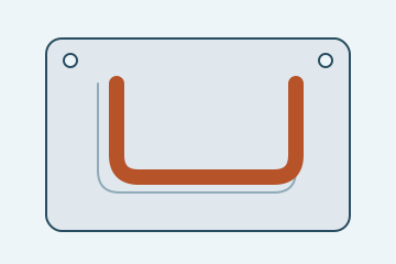
The bead moves away from the part-based reference.
Select an image to view it at full size.
Inspect the glue path in its own coordinate system
Explore Glue bead inspection and Assembly verification to connect this inspection task with the wider station requirements.
Swipe across the table to compare all columns →
| Decision | Evidence to use | Rule to agree |
|---|---|---|
| Continuity correct | Inspect the required path including corners. | Exclude only intentional gaps. |
| Position correct | Compare with the part-based route. | Do not align the reference to the bead itself. |
| Geometry correct | Evaluate width or calibrated height as specified. | Avoid inferring volume from brightness. |
Separate a missing bead from a missing scan segment
For a visible bead on a contrasting surface, 2D imaging may establish lateral position and continuity. Height or cross-sectional requirements can justify 3D, but only where the sensor obtains valid depth data. Reflective or shadowed regions can produce missing scan points without proving that glue is absent.
Treat corners and the start/end junction as their own geometric contexts. Their acceptable shape may differ from a straight run. Verify scan coverage along the path before interpreting a gap, and keep the local part reference stable through any stitching between views.
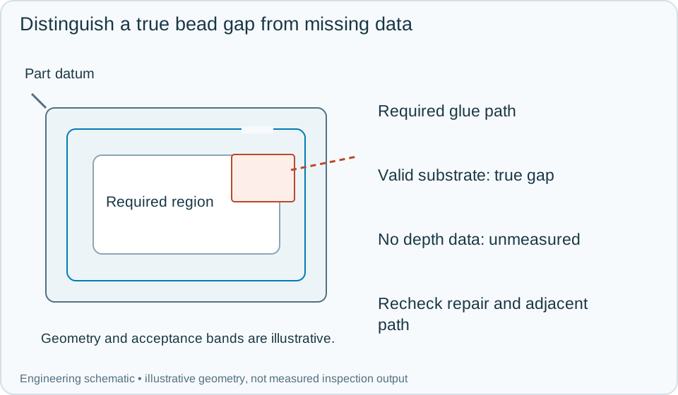
On a small screen, scroll across the diagram to inspect the labels.
Swipe across the table to compare all columns →
| Approach | Useful when | What to validate |
|---|---|---|
| 2D contrast inspection | Presence, visible width and path are sufficient. | Test adhesive/substrate contrast. |
| 3D profile inspection | Height or section geometry is required. | Validate the base surface and occlusion. |
| Robot-guided acquisition | The complete route cannot fit one fixed view. | Check synchronisation and segment coverage. |
Worked example: the bead appears to break at a corner
In an illustrative inspection, the straight sections are complete but the corner contains no height points. The coverage mask shows invalid data, so the station returns unmeasured corner rather than confirmed missing glue. Reacquire from a qualified view or hold the part for the agreed check.
A second corner has valid surface data showing the substrate where glue is required. That is evidence for a true continuity fault. A third has continuous glue shifted outside the allowed route and fails position instead. If repair is authorised, reinspect the repaired area plus the defined overlap with adjacent path segments, and repeat full-path checks where the process requires them. Preserve the original fault, repair attempt and final part decision.
Swipe across the table to compare all columns →
| Observed evidence | Inspection decision | Action and retained record |
|---|---|---|
| The apparent bead gap has no valid depth returns rather than visible substrate. | Coverage gap; missing glue is unproven. | Retain the validity mask and path coordinate, reacquire through the approved view or hold the part for the assigned check. |
| Valid substrate is observed where the required glue path should be continuous. | True continuity fault under the agreed path rule. | Store the affected interval, hold for authorised repair or rejection and recheck the repaired region with the required adjacent overlap. |
| The bead is continuous but displaced outside its permitted route. | Position failure independent of continuity. | Keep the part datum and path deviation, apply the defined handling action and preserve both original and post-repair results. |
How should a missing or displaced bead be handled?
- 01Locate the partAnchor the bead route to stable datums.
- 02Inspect the exposed pathAcquire all required segments.
- 03Separate fault typesEvaluate continuity, position and geometry.
- 04Hold for reworkKeep the defect location before mating.
Inspect after dispensing at a point where the full path is exposed. If a robot moves the camera or sensor, synchronise the acquired segments to the part and verify coverage at joins. A missing segment must not be interpreted as a good empty image. Keep the fault position available for rework before mating the components hides the bead.
Challenge the path's transitions and recovery rules
Include thin sections, true gaps, displaced beads, acceptable corner shapes and deliberately missing scan data. Verify that the complete required path has valid evidence before release.
A visible bead or qualified profile does not by itself establish cure, adhesion or sealing performance. Assign those properties to their required process controls or tests, and compare vision architectures according to the observable geometry and coverage they add.
Swipe across the table to compare all columns →
| Challenge | What the trial should establish |
|---|---|
| Good bead variation at corners | Define permitted geometry changes. |
| Short breaks and shifted sections | Verify local fault detection. |
| Reflective parts and aged wet samples | Challenge appearance changes. |
| Missing scan segment or rework attempt | Confirm coverage and revised disposition. |
Why a bead image cannot prove bond strength
Visible continuity and geometry do not prove adhesive cure, bond strength or sealing performance. A 2D width check needs a stated view and reference; a 3D height check needs calibration and a reliable base surface. Evaluate these separately from the dispensing recipe and material-process controls.
Use Vision measurement vs CMM and gauges to develop the related acceptance and integration questions for your trial.
Bead paths and corner variations for a trial
Provide part datums, required paths and intentional gaps, wet adhesive samples, confirmed breaks and offsets, width/height requirements and the time available before assembly.
Use the optical and recovery challenges above when applying the architecture choices in HIKROBOT and other vision solutions comparison.
Scope and budget
Use the glue bead inspection scope and cost factors to scope bead-path coverage, part localisation and the handling of an interrupted glue route.
Testing and handover
The testing and handover process should include displaced beads, difficult corners and the separate bond or leakage tests required by the product.