Application guide by addaScanCompare the inspection task, imaging conditions and validation steps with your own production line.
- Task
- Transparent film defect inspection
- Decision focus
- Web inspection
- Workflow
- Identify trim and intentional features.
- Validation
- Accepted film across production lots
Specks, holes and optical variation in transparent film
Original explanatory diagrams show the product states and inspection questions. They are schematics, not captured inspection results.

Accepted material defines the optical background.

A dark inclusion contrasts in a suitable transmitted view.

A puncture requires contrast against the chosen background.
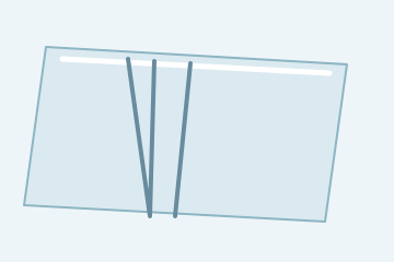
A folded region changes the reflected-light response.
Select an image to view it at full size.
Choose light that reveals the particular transparent-film fault
Use the plastics and packaging guide to place transparent-film inspection within the extrusion or converting workflow and define the material reference.
Define the inspection scope before choosing the station layout.
Swipe across the table to compare all columns →
| Decision | Evidence to use | Rule to agree |
|---|---|---|
| Local contamination | Detect agreed visible inclusions. | Challenge particles near the accepted texture level. |
| Material discontinuity | Assess holes under useful contrast. | Do not assume every clear puncture is visible. |
| Shape disturbance | Evaluate wrinkles in the real tension state. | Distinguish normal web movement from a defect. |
Compare transmission and reflection under real web tension
Transmitted illumination can emphasise opaque contamination or changes in transmitted light, but the response of a hole depends on the film and background. Oblique reflected light can reveal slope changes at a wrinkle. Use known samples to verify both instead of assuming a bright or dark spot always represents the same defect.
Keep web tension, support and vibration within the tested presentation range. A temporary wave caused by handling is not automatically a permanent material crease. Whether it is acceptable depends on the process requirement, but its cause matters when deciding between mechanical correction and defect rejection. Preserve material coordinates through both lighting views.
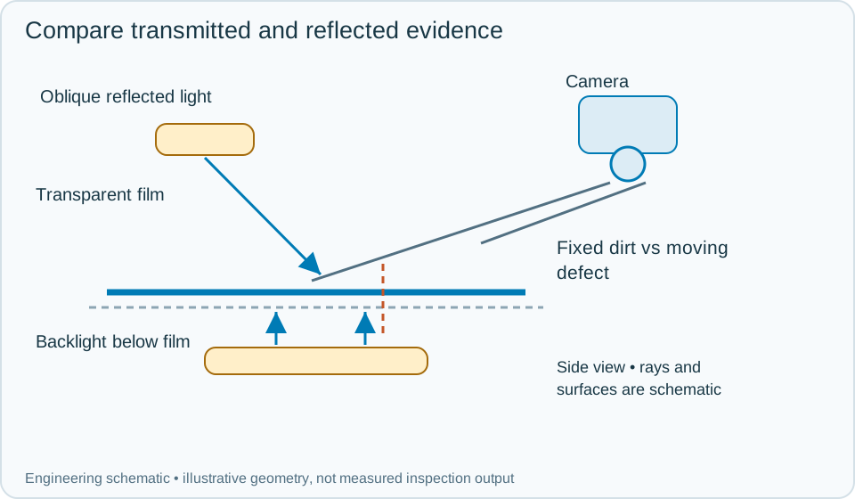
On a small screen, scroll across the diagram to inspect the labels.
Swipe across the table to compare all columns →
| Approach | Useful when | What to validate |
|---|---|---|
| Transmitted illumination | Inclusions or openings contrast with the background. | Keep the optical background clean. |
| Angled reflected illumination | Surface slope changes are important. | Test both wrinkle orientations. |
| Multiple optical channels | Different defects need different responses. | Align channels to the same web location. |
Worked example: a dark spot stays fixed while the film moves
In an illustrative sequence, a suspected spot remains at the same image location as identifiable film features advance. Inspect the background and optical window; the evidence points towards station contamination rather than a moving material defect. Restore the view and recheck any interval whose required area was obscured.
Another spot travels with the film and meets the contamination criterion, so record its material position and contain the affected interval. A third feature appears only when tension drops and the film bows. Compare it with approved tension variation and real crease samples before assigning a permanent-defect label. Retain the image sequence, tension condition where available and final handling decision so the operator can distinguish these causes.
Swipe across the table to compare all columns →
| Observed evidence | Inspection decision | Action and retained record |
|---|---|---|
| A dark feature advances with the web through registered images. | Material-fixed contamination candidate. | Apply the agreed defect rule and store the material interval, supporting sequence and downstream segregation or roll-review action. |
| The feature stays fixed while identifiable film texture advances. | Background or optical contamination is suspected. | Inspect and clean through the approved process, record obscured coverage and recheck affected material rather than accepting missing evidence. |
| A slope feature appears during low tension but disappears after restoring presentation. | Handling-induced wave must be separated from permanent crease criteria. | Retain the tension condition and image sequence, compare approved waves and real creases and document the final material decision. |
How should a film defect be mapped to the correct web length?
- 01Define usable widthIdentify trim and intentional features.
- 02Acquire optical channelsReveal the specified defect classes.
- 03Map each findingUse cross-web and length coordinates.
- 04Mark or hold the roll sectionKeep the position valid through winding.
Use the motion reference to map a detection to its length and cross-web position. Preserve those coordinates through slowing, stopping and winding. A dirty background or damaged roller can create recurring image features, so include checks that distinguish stationary contamination in the imaging system from a defect travelling with the film.
Validate holes against the actual background
Include known holes, dark particles, permanent creases, acceptable waves and dirty-window conditions across the allowed tension range. Verify missing-frame handling and position mapping to the downstream roll or cut piece.
A more complex model does not compensate for a transparent hole that has no visible contrast in the chosen optical setup. Change the illumination or inspection arrangement first, then assess classification on the usable evidence.
Swipe across the table to compare all columns →
| Challenge | What the trial should establish |
|---|---|
| Accepted film across production lots | Characterise optical variation. |
| Specks and holes across the width | Verify contrast and edge coverage. |
| Wrinkles under operating tension | Test sensitivity to mechanical presentation. |
| Dirty background and speed changes | Separate equipment artefacts from material defects. |
What a film image cannot confirm
A two-dimensional defect image does not establish film thickness or barrier performance. If those properties determine acceptance, specify separate measurement or test equipment. Detection examples from metal foil or coated electrodes cannot establish performance on transparent film without material-specific trials.
Use Web and line-scan inspection to develop the related acceptance and integration questions for your trial.
Film samples and web conditions to provide
Provide each film structure, thickness range as a process input, good optical variation, actual specks, punctures and wrinkles, plus tension, roller and rewind information.
Use the optical and recovery challenges above when applying the architecture choices in HIKROBOT and other vision solutions comparison.
Scope and budget
The vision system cost guide helps assess continuous image capture, web tracking and any marking or downstream handling interface.
Testing and handover
Use the testing and handover process to test glare, lost position and restart behaviour without merging events from different web lengths.