Application guide by addaScanCompare the inspection task, imaging conditions and validation steps with your own production line.
- Task
- Thread and fastener profile inspection
- Decision focus
- Thread inspection
- Workflow
- Select the correct fastener recipe.
- Validation
- Good lead-in and run-out variation
Thread crests, spacing and the visible side profile
Original explanatory diagrams show the product states and inspection questions. They are schematics, not captured inspection results.
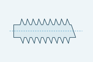
Visible thread features follow the recipe.
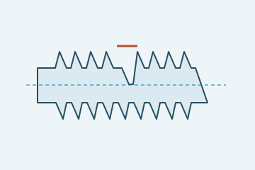
A local interruption changes the side contour.
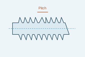
Feature spacing must be measured from a stable reference.
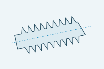
Presentation changes the apparent geometry.
Select an image to view it at full size.
Establish the fastener axis before judging thread peaks
Explore Fastener inspection and Dimensional measurement to connect this inspection task with the wider station requirements.
Swipe across the table to compare all columns →
| Decision | Evidence to use | Rule to agree |
|---|---|---|
| Correct fastener | Identify family and orientation. | Hold an unknown or inverted part. |
| Visible thread condition | Evaluate required crest and contour regions. | Exclude intentional lead-in and run-out. |
| Specified dimensions | Measure agreed features after calibration. | Keep functional gauging requirements separate. |
Allocate visible geometry and functional gauging separately
A backlit profile can expose external peaks and certain missing or damaged sections. Correct only validated pose variation using the part axis, then evaluate the required intervals. Normal runout is a designed transition, not a broken full thread. A single silhouette does not cover every circumferential surface or establish internal thread function.
Multiple angular views can increase external coverage, provided they remain associated with the same fastener and known orientation. Functional fit may still require a go/no-go gauge or another specified test. Choose 2D, additional views and gauging according to the actual drawing requirements rather than presenting them as interchangeable quality checks.
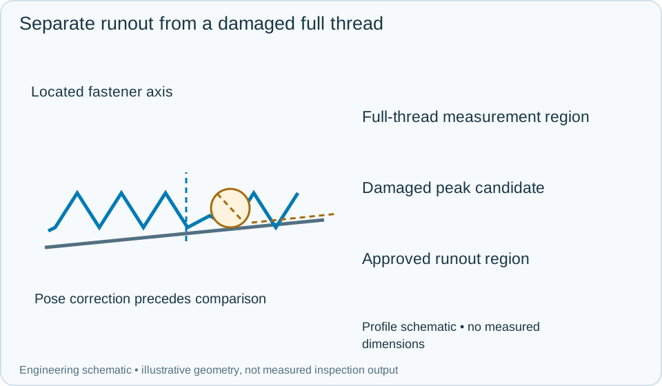
On a small screen, scroll across the diagram to inspect the labels.
Swipe across the table to compare all columns →
| Approach | Useful when | What to validate |
|---|---|---|
| Backlit profile | External geometry is visible from the side. | Challenge tilt and far-side defects. |
| Rotated or multiple views | More circumferential coverage is required. | Validate complete coverage per part. |
| Combined vision and gauges | Visible checks and functional fit both matter. | Assign each acceptance rule to the appropriate method. |
Worked example: a low peak occurs at the thread runout
In an illustrative fastener, a low peak appears inside the approved runout region. Its location relative to the part datum makes it a permitted transition. A similar low peak in the required full-thread region is assessed as a damage candidate under the agreed profile rule.
If the axis locator fails because the part is partly outside the image, neither conclusion is valid. Re-present and inspect the identified part again. For a multi-view sequence, a missing angle leaves the assigned surface coverage incomplete even if all available profiles pass. Store the datum, inspected interval, angular view and measured evidence with the final handling action. A functional gauge failure remains a failure even when the visible profile looks acceptable.
Swipe across the table to compare all columns →
| Observed evidence | Inspection decision | Action and retained record |
|---|---|---|
| A reduced peak lies inside the approved runout interval after valid axis location. | Designed transition may be acceptable under the drawing rule. | Store the axis and interval reference and inspect the required full-thread region independently rather than widening all profile limits. |
| A damaged peak appears within the required full-thread region in a qualified view. | Visible profile fault. | Retain the angular view and local contour, reject or hold the fastener and keep any functional-gauge result as a separate requirement. |
| The part is tilted beyond the validated locating range or partly outside the image. | Profile evidence invalid. | Re-present the same fastener and reacquire; do not use an unconstrained pose correction to reduce an apparent damage feature. |
When should a fastener profile result trigger a recheck?
- 01Identify and orientSelect the correct fastener recipe.
- 02Capture the profileControl tilt and image geometry.
- 03Measure and classifySeparate dimensions from visible thread faults.
- 04Sort the same partConfirm routing and retain failure reasons.
Find the axis and defined end reference before measuring the required features. Keep pitch, major-profile dimensions and local thread defects as separate results so a failure can be diagnosed. At the sorter, track each fastener and confirm that the selected discharge action matches the measured part.
Challenge pose and damage independently
Use accepted runout variations, known broken peaks, tilted parts and repeated loading. Compare dimensional results with an appropriate reference method, and test whether a pose correction accidentally reduces a real defect.
Retain separate visible-profile and functional-test outcomes. That separation gives the customer a precise account of what the vision station establishes and where another inspection method remains necessary.
Swipe across the table to compare all columns →
| Challenge | What the trial should establish |
|---|---|
| Good lead-in and run-out variation | Avoid classifying intended geometry as damage. |
| Damaged threads around the circumference | Establish actual coverage. |
| Tilt and feeding variation | Measure repeatability under production handling. |
| Mixed fastener types and reject faults | Verify recipe selection and physical sorting. |
What an external profile cannot reveal
Do not describe a silhouette measurement as complete functional thread gauging. Internal threads, hidden flank damage and defects away from the observed envelope may need other methods. A calibration image also does not demonstrate production repeatability; test the real feeding and seating variation.
Use Vision measurement vs CMM and gauges to develop the related acceptance and integration questions for your trial.
Fastener drawings and profile samples for a trial
The metal components and fabrication guide helps place visible fastener-profile checks within the part's manufacturing and quality-control route.
Provide drawings and tolerances, accepted lead-in/run-out examples, damaged crests, all fastener families, reference measurements and the proposed feeding arrangement.
Use the optical and recovery challenges above when applying the architecture choices in HIKROBOT and other vision solutions comparison.
Scope and budget
The fastener inspection scope and cost factors helps separate visible profile measurement from internal or hidden fastener features.
Testing and handover
Include permitted pose changes, reference profiles and borderline measurements in the testing and handover process.