Application guide by addaScanCompare the inspection task, imaging conditions and validation steps with your own production line.
- Task
- Upper and lower PCB reader integration
- Decision focus
- DPM reader
- Workflow
- Load the expected code locations and data rule.
- Validation
- Board families with codes on either face
Upper and lower reads must belong to the same PCB
Original explanatory diagrams show the product states and inspection questions. They are schematics, not captured inspection results.
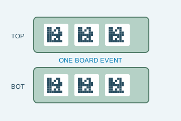
Both views contribute to the same board event.
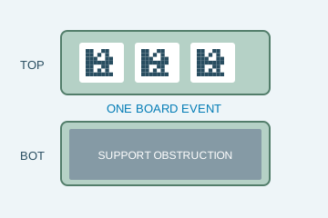
Conveyor geometry blocks a required view.
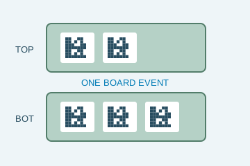
One read does not establish all required identities.
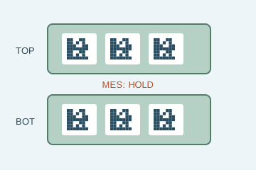
Readable data still fails the production rule.
Select an image to view it at full size.
Join upper and lower PCB reads under one board event
Explore DPM code reading and Code reader selection to connect this inspection task with the wider station requirements.
Swipe across the table to compare all columns →
| Decision | Evidence to use | Rule to agree |
|---|---|---|
| Required codes acquired | Collect the identifier set defined for the panel. | Do not assume the first code is sufficient. |
| Views associated | Bind upper and lower results to one board event. | Reject stale or ambiguous combinations. |
| MES accepted | Wait for the matching business-rule response. | Hold on mismatch or timeout. |
Define completion before releasing the board
Create the board event from the controlled handling or trigger sequence, then assign both acquisitions to it. The recipe should state which side supplies which identities and, for a panel, how many sub-board positions are expected. Store side, position, request identifier and result status with each observation.
Two readers simplify access to opposite surfaces but add synchronisation and buffering duties. A controller or application must own the completion state and timeout behaviour. If a board can move before both sides finish, provide an identified buffer or stop condition. A general success bit from each reader is insufficient without event correlation.
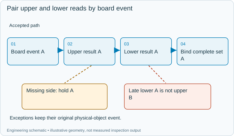
On a small screen, scroll across the diagram to inspect the labels.
Swipe across the table to compare all columns →
| Approach | Useful when | What to validate |
|---|---|---|
| One reader | The required code face is controlled and visible. | Check family-dependent face changes. |
| Upper and lower readers | Either face or both faces contain required data. | Validate support occlusion and event timing. |
| Reader controller with MES interface | Multiple results and transfer decisions must be coordinated. | Specify full-set versus selected-ID output. |
Worked example: the previous lower result arrives late
In an illustrative sequence, board A's upper read completes but its lower read is delayed. Board B then reaches the upper station. A's lower response must complete or remain attached to A; it cannot be paired with B's new upper identity.
If A exceeds its permitted completion window, hold or route it through the agreed exception process. Reinspection should create a controlled attempt while preserving A's identity and previous observations. Missing sub-board positions leave a panel incomplete even if both readers have returned some codes. Submit the required complete set and wait for the binding response before issuing the final release. An operator reset should reconcile held physical boards and clear only the appropriate pending state.
Swipe across the table to compare all columns →
| Observed evidence | Inspection decision | Action and retained record |
|---|---|---|
| Board A's lower result arrives after board B's upper result. | Responses belong to different board events. | Keep them separate, complete or reconcile A under its original event and leave B pending until B's own required lower result arrives. |
| Both readers return some codes but one required sub-board position is unresolved. | Panel set remains incomplete. | Retain side and position status, hold the board or use an identified buffer and resolve every required identity before binding. |
| An operator resets the interface while a board remains between readers. | Physical boards and pending event state need reconciliation. | Record the reset, identify held boards and clear only the appropriate state before restarting the qualified complete-set sequence. |
What happens when reader results arrive out of order?
- 01Create the board eventLoad the expected code locations and data rule.
- 02Acquire both facesTrack completion from each required reader.
- 03Build and validate the setSend only the agreed event data to MES.
- 04Control board transferRelease after the matching accepted response.
Trigger both readers from the same board event and define completion, no-read and timeout states. Buffer results by board identity or event sequence; do not combine a late lower read from one board with the next upper read. Send the agreed identifier set to MES and use its response to control the transfer equipment through a specified interface.
Validate partial sets and restart boundaries
Delay one side, drop a frame, duplicate a response and stop with a board between stations. Confirm that neither the next board nor a partial panel inherits an old value.
Retain board events, side-specific images, expected position maps, timeout reasons and final MES acknowledgements. Compare reader systems on this full workflow as well as optical performance, because correct individual strings do not prove a correct combined board record.
Swipe across the table to compare all columns →
| Challenge | What the trial should establish |
|---|---|
| Board families with codes on either face | Verify optical coverage. |
| Missing child code or duplicated identifier | Check set-completeness rules. |
| Late reader result and close board spacing | Prevent mixed-board data. |
| MES timeout, mismatch and manual reset | Validate transfer hold and recovery. |
What paired code reads cannot prove about a PCB
Reading a PCB identifier does not inspect solder joints or establish electrical function. The MES handshake also needs recovery rules: a successful read followed by an unconfirmed network transaction is different from an accepted board. Manual reset should clear the exception only through the agreed reconciliation process.
Use Barcode verification and grading to develop the related acceptance and integration questions for your trial.
Board codes and reader timing to provide
Provide panel layouts, top/bottom code examples, the required identifier set, board spacing, support geometry, MES message definitions and the intended stop/reset behaviour.
Use the optical and recovery challenges above when applying the architecture choices in HIKROBOT and other vision solutions comparison.
Scope and budget
Use the vision system cost guide to separate reader hardware from trigger coordination, result pairing and line-interface work.
Testing and handover
Include out-of-order messages, a missing result and a restart between board events in the testing and handover process.
The envelope verification project documents identity matching and integration checks at FAT. Review that event-association problem when defining how two reader results belong to one board.