Application guide by addaScanCompare the inspection task, imaging conditions and validation steps with your own production line.
- Task
- Scratch detection on aluminium extrusions
- Decision focus
- Scratch detection
- Workflow
- Use the appropriate surface reference.
- Validation
- Good brushing and die lines
Scratches against the extrusion’s normal grain
Original explanatory diagrams show the product states and inspection questions. They are schematics, not captured inspection results.
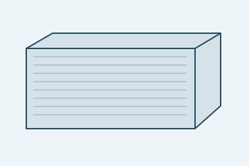
Parallel finish texture forms the good reference.

A local mark interrupts the regular texture.
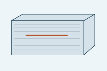
The defect can blend into the normal pattern.
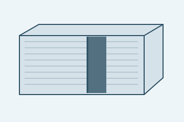
Geometry can hide a face from one view.
Select an image to view it at full size.
Make scratches visible across the extrusion's surface directions
Explore Surface defect detection and Aluminium extrusion surface inspection to connect this inspection task with the wider station requirements.
Swipe across the table to compare all columns →
| Decision | Evidence to use | Rule to agree |
|---|---|---|
| Surface reference | Select the correct profile face and finish. | Keep normal texture in the good set. |
| Scratch-like feature | Compare contrast, extent and morphology with agreed defects. | Challenge both grain directions. |
| Location for action | Record the affected face and material position. | Preserve identity through cutting. |
Match the light path to the profile geometry
Low-angle illumination can reveal relief, but the extrusion itself may shadow grooves or hide a side face. Map required surfaces on the cross-section and compare lighting directions with the same known faults. If a face remains hidden, add a view or change presentation; increasing algorithm sensitivity cannot restore it.
Separate recipes for materially different surface treatments where their normal appearance changes. A trained tool may accommodate accepted texture variation, while directional feature checks can work for stable finishes. In either case, keep the extrusion coordinate and longitudinal material position so a detected scratch can be mapped to a cut piece.
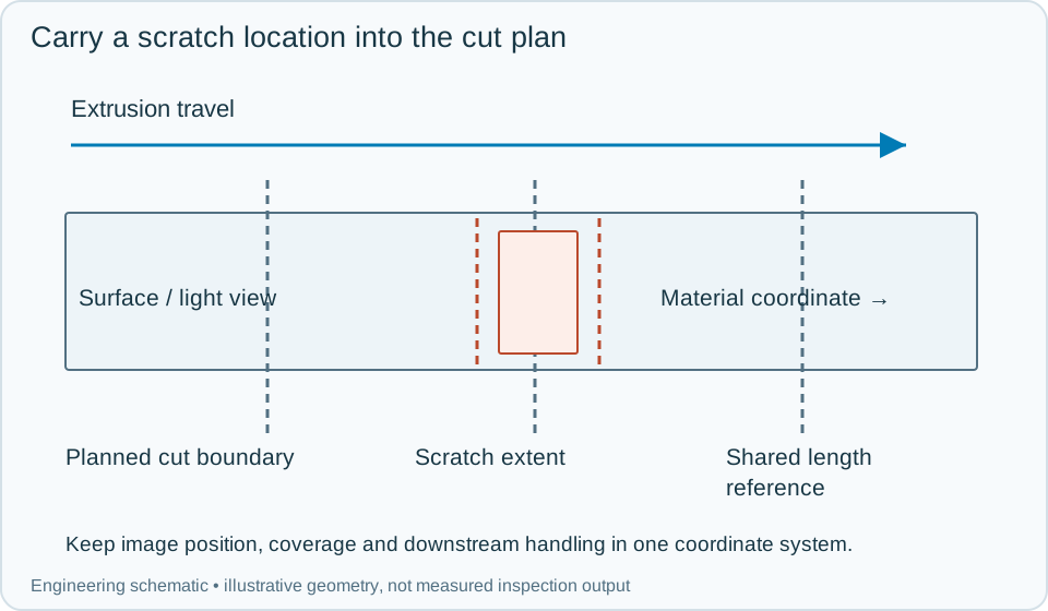
On a small screen, scroll across the diagram to inspect the labels.
Swipe across the table to compare all columns →
| Approach | Useful when | What to validate |
|---|---|---|
| Single oblique light | Target scratches contrast in the required orientation. | Check the weak-contrast direction. |
| Multiple lighting directions | Different defect orientations need different contrast. | Associate images with the same material region. |
| Line scan | Continuous length needs position-resolved inspection. | Coordinate motion, line acquisition and defect location. |
Worked example: a faint scratch spans a cut boundary
In an illustrative run, a scratch parallel to the finish is weak under one light but clear under the qualified complementary view. Merge the registered evidence at the same surface location. Record its longitudinal extent and uncertainty, then intersect that interval with the planned cut lengths.
If the affected interval crosses a cut boundary, contain the relevant pieces under the agreed rule rather than assigning the whole defect to its centre point. A missing encoder reference interrupts trustworthy mapping even if the scratch detector still works. Mark the uncertain material interval and reconcile it before normal release resumes. Retain the surface view, defect extent, cut identifiers and confirmation of marking or segregation.
Swipe across the table to compare all columns →
| Observed evidence | Inspection decision | Action and retained record |
|---|---|---|
| A scratch appears only under the qualified complementary light on its surface face. | Visible defect evidence despite a clean first view. | Retain the registered light pair and surface identifier. Apply the defect rule and map its extent into the shared cut coordinate. |
| A groove wall remains hidden under every installed view. | Required surface coverage is missing. | Record the unobserved face and change presentation or add a qualified view. No-detection output cannot establish acceptance of that surface. |
| The scratch interval and its position uncertainty cross a planned cut boundary. | More than one downstream piece may be affected. | Store interval and cut identifiers, verify physical segregation and reconcile tracking after any encoder or cut-plan interruption. |
How should an ambiguous extrusion mark be handled?
- 01Select finish and faceUse the appropriate surface reference.
- 02Illuminate the textureReveal the required defect directions.
- 03Locate suspicious marksRecord the affected face and length position.
- 04Mark or isolateAct on the correct profile or cut length.
For continuous profiles, associate the defect with a material position using the line-motion reference. Preserve that position through cutting or marking so the correct length can be isolated. For discrete parts, locate the profile and retain face identity; an edge reflection should not be analysed as a flat cosmetic surface.
Test the hardest visible face and the tracking handoff
Include along-texture and cross-texture scratches, grooves, acceptable finish changes, line stops and cut-plan changes. Verify the physical defect location against the recorded cut piece.
Keep optical coverage failures distinct from accepted smooth surfaces. Visible scratch inspection does not establish dimensional straightness or other profile requirements; assign those to their own measurement process rather than broadening the appearance result.
Swipe across the table to compare all columns →
| Challenge | What the trial should establish |
|---|---|
| Good brushing and die lines | Measure false rejects on accepted variation. |
| Scratches along and across grain | Identify lighting blind spots. |
| Corners and recessed faces | Document coverage limits. |
| Line speed change and cut transfer | Verify the correct length is marked or held. |
What surface images cannot tell you about scratch depth
An image can show a scratch-like feature without measuring its depth. If depth determines acceptance, evaluate a suitable measurement method. A model trained on one finish or brushing direction needs fresh validation before use on another, even when the nominal profile shape is identical.
Use Machine vision lighting to develop the related acceptance and integration questions for your trial.
Extrusion finishes and scratch samples to test
The metal components and fabrication guide connects extrusion surface checks with fabrication and finishing. Choose the inspection point for the surface condition that actually needs acceptance.
Supply accepted die lines and brushing, confirmed scratches in different directions, all surface finishes, profile cross-sections and the marking or cutting sequence.
Use the optical and recovery challenges above when applying the architecture choices in HIKROBOT and other vision solutions comparison.
Scope and budget
Use the aluminium extrusion surface inspection scope and cost factors to compare coverage, surface finish and tracking of the affected extrusion length.
Testing and handover
The testing and handover process should test the surface state at the chosen inspection point, including inspection before powder coating or anodising when that is the required stage.