Application guide by addaScanCompare the inspection task, imaging conditions and validation steps with your own production line.
- Task
- Multi-light glass cover inspection
- Decision focus
- Surface defect detection
- Workflow
- Load the glass-family inspection map.
- Validation
- Normal coating and print borders
Different lighting reveals different glass defects
Original explanatory diagrams show the product states and inspection questions. They are schematics, not captured inspection results.
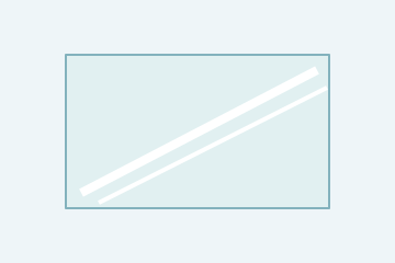
The required region is visible under the selected light.
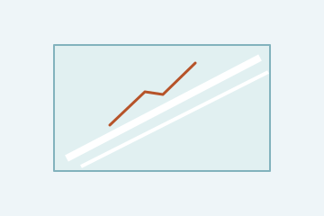
A light direction reveals a surface discontinuity.
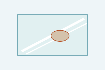
Another lighting condition may better expose contamination.
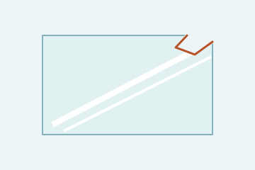
The edge needs a distinct geometric inspection region.
Select an image to view it at full size.
Compare multiple lights on the same glass location
Explore Surface defect detection and Machine vision lighting to connect this inspection task with the wider station requirements.
Swipe across the table to compare all columns →
| Decision | Evidence to use | Rule to agree |
|---|---|---|
| Surface feature | Compare the relevant lighting response with agreed samples. | Retain the light and face identity. |
| Edge condition | Inspect the specified perimeter geometry. | Do not merge it with a surface-texture score. |
| Exposure completeness | Require all necessary images for this part. | Hold missing or misregistered exposures. |
Assign a purpose to each illumination view
Directional illumination can reveal scratches whose contrast depends on their orientation. A broader reflectance view may better expose stains, while an edge view or silhouette can support chip detection. Test these responses on the same accepted and defective samples instead of assuming one light reveals every class.
Keep exposure order and part pose with the image set. Verify registration before combining results, and distinguish surface features from contamination on the background or optical window. A mark that remains fixed while the glass shifts may belong to the station. Enough usable evidence must remain to inspect the required glass area after excluding such interference.
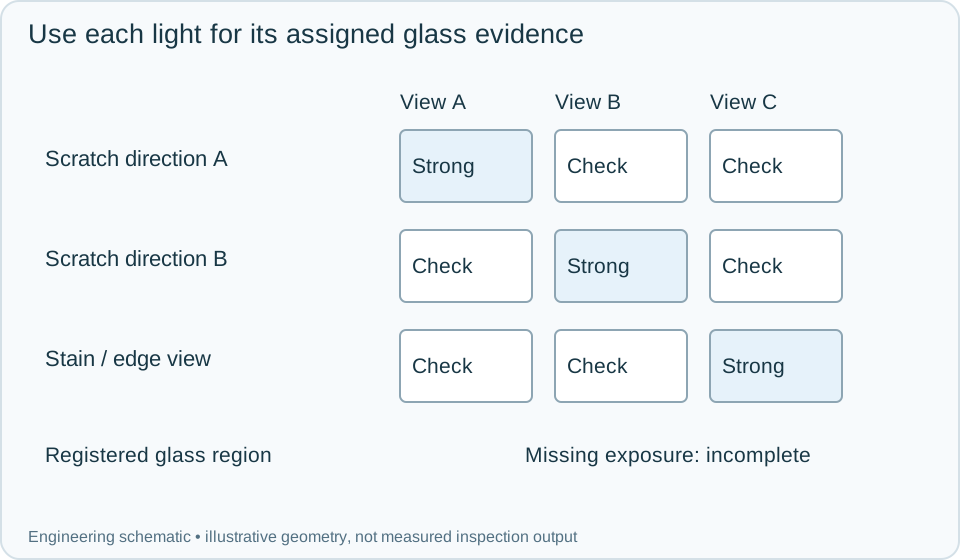
On a small screen, scroll across the diagram to inspect the labels.
Swipe across the table to compare all columns →
| Approach | Useful when | What to validate |
|---|---|---|
| Single light | One defined defect class has reliable contrast. | Do not infer coverage of other classes. |
| Sequential lighting | Multiple optical responses are needed at one position. | Manage movement between exposures. |
| Separate views or stations | Faces and edges cannot share a useful view. | Track the same glass through every check. |
Worked example: one exposure is missing after the glass moves
In an illustrative sequence, two light views arrive but the third is absent. The available views show no fault, yet the defect class assigned to the missing view has not been inspected. Hold the part or reacquire a complete qualified sequence.
If the glass moved between views, first establish whether registration can recover the same physical regions within the validated limits. Otherwise restart the acquisition for that part. A scratch found only in its effective light direction can fail the part without also appearing in every other view. Retain the selected evidence and the complete exposure-validity record. After removing background contamination, recheck affected parts rather than retroactively relabelling their obscured images as good.
Swipe across the table to compare all columns →
| Observed evidence | Inspection decision | Action and retained record |
|---|---|---|
| A scratch is visible in its effective directional light but weak in the other views. | One qualified view can supply sufficient defect evidence. | Keep the registered image set and fault location, reject the glass and avoid requiring the fault to appear under ineffective illumination. |
| One mandatory exposure is missing while the available views appear normal. | The assigned defect coverage is incomplete. | Hold or reacquire a complete set for the same part. Store exposure status and prevent a frame from the next part filling the gap. |
| A spot remains fixed when the glass moves relative to the background. | Station contamination is suspected rather than a glass-fixed defect. | Restore the optical path, preserve the ambiguous images and recheck any glass area whose required evidence was obscured. |
How should results from different lights be combined?
- 01Define faces and regionsLoad the glass-family inspection map.
- 02Acquire required lightsKeep exposures aligned to the same part.
- 03Classify by regionPreserve defect location and illumination identity.
- 04Complete the decisionRelease only after required views finish.
Register each view to a stable part reference and retain which illumination produced the finding. A missing exposure should not be replaced by a previous part image. When combining results, allow the necessary inspection regions and lighting states to complete before releasing the glass. Record the location so a quality operator can reproduce the observation.
Challenge direction, contamination and sequence integrity
Include scratches parallel and transverse to each light direction, stains, edge chips, clean glass and dirty background conditions. Interrupt an exposure and shift the part deliberately to verify that the station detects an invalid set.
A multi-light system adds value when each view answers a specified requirement. It also adds timing and registration obligations; compare those complete obligations when selecting a smart camera or a more flexible multi-camera system.
Swipe across the table to compare all columns →
| Challenge | What the trial should establish |
|---|---|
| Normal coating and print borders | Establish the accepted reference by region. |
| Scratches at different orientations | Find weak-contrast lighting conditions. |
| Dust, stains and edge chips | Check class separation and position reporting. |
| Missing exposure or shifted glass | Verify incomplete coverage prevents release. |
Where a glass surface check needs another method
Visible blemish inspection does not establish coating thickness, optical transmission or glass strength. If the requirement is a physical dimension rather than cosmetic appearance, specify a measurement method. Scratches on a glossy surface also need a clear customer acceptance reference; image contrast is not automatically scratch depth.
Use Machine vision lighting to develop the related acceptance and integration questions for your trial.
Glass finishes and defect types to compare
Provide accepted surface variation, scratches in several directions, stains, edge chips, coated and printed variants, cleaning conditions and the required face coverage.
Use the optical and recovery challenges above when applying the architecture choices in HIKROBOT and other vision solutions comparison.
Scope and budget
Use the vision system cost guide to compare lighting channels, view alignment and image-processing requirements for the glass finish.
Testing and handover
Agree how conflicting observations across lights are resolved in the testing and handover process.