Application guide by addaScanCompare the inspection task, imaging conditions and validation steps with your own production line.
- Inspection task
- Plastic pipe inkjet inspection
- Decision focus
- plastic pipe inkjet inspection
- Station planning
- Define the inspected length and the cutting coordinate
- Illustrative scenario
- a missing print falls near a cut boundary
Accepted and rejected marks on curved pipe surfaces
The application images show the physical product and imaging conditions. The engineering diagram below explains the inspection logic and recovery decisions.
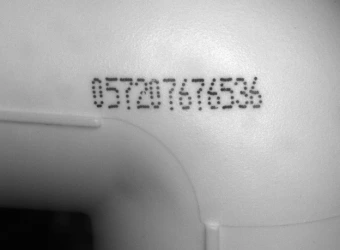
This captured pipe-fitting mark illustrates an acceptable print example.
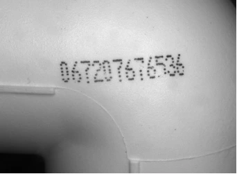
This curved-surface mark illustrates an unacceptable print example. Compare its strokes with the accepted sample.
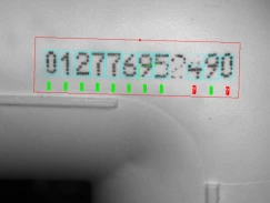
Selected image area from the NG inspection screen; the original character overlays remain intact.
Select an image to view it at full size.
Track a printing fault to the pipe that leaves the line
Swipe across the table to compare all columns →
| Condition | Approach to evaluate | Selection check |
|---|---|---|
| Readable but wrong characters | Compare the string with the current production reference. | A clean image does not establish correct content. |
| Missing or blurred strokes | Evaluate OCR confidence together with print-condition checks. | Include borderline acceptable inkjet dots. |
| Mark wanders around a curved wall | Compare presentation control and additional views. | Do not assume one camera covers a hidden surface. |
Define the inspected length and the cutting coordinate
For discrete parts, trigger when the required printed region is in view and bind the result to that part. For continuous material, relate camera events to an encoder or another validated length reference. Record the print repeat position and the cut boundaries in the same coordinate system, including the offset between inspection and cutting.
A round pipe may rotate so that the print moves away from the visible surface. Guiding the pipe or adding circumferential coverage can restore visibility; enlarging the image alone may sacrifice character detail. If the process can print on an unpredictable hidden side, a single fixed view cannot establish complete coverage. Include that condition as unavailable inspection rather than a missing-print conclusion.
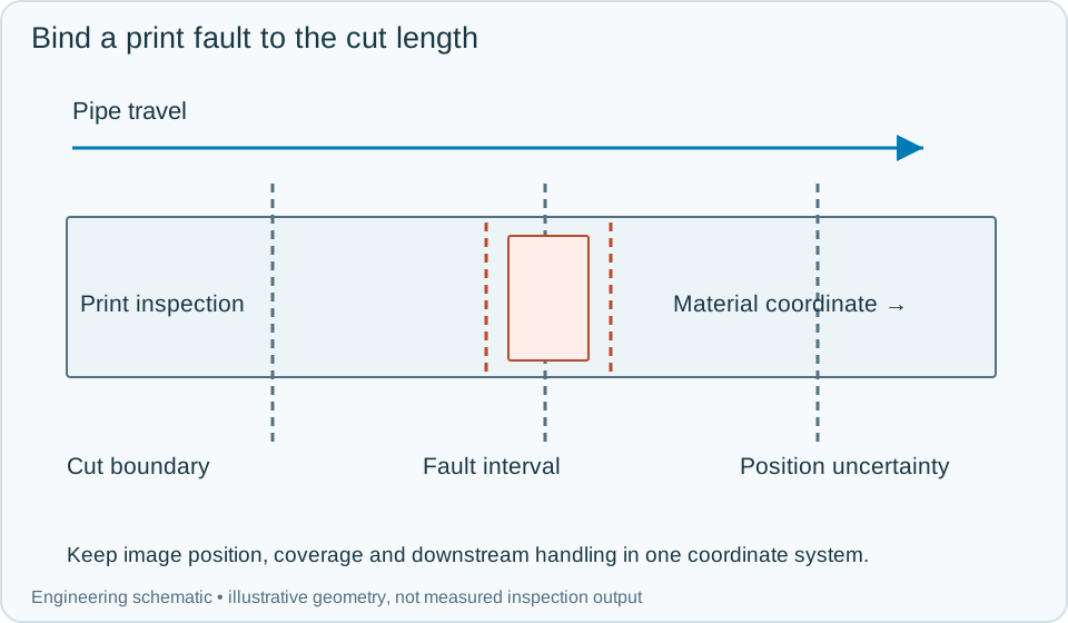
On a small screen, scroll across the diagram to inspect the labels.
Worked example: a missing print falls near a cut boundary
In an illustrative continuous run, a valid image shows an incomplete code at a known line coordinate. Associate the affected printed region, including position uncertainty, with the planned cut intervals. If that uncertainty overlaps a boundary, contain the potentially affected pieces according to the agreed rule instead of selecting only the nearest cut centre.
A later frame is missing after an encoder interruption. Record an uninspected interval, not a good print. Recover the coordinate reference before resuming normal acceptance. If the line has already cut material while position was uncertain, reconcile the physical pieces with the quarantine interval. Store the defect image, encoder position, cut identifiers and confirmation that the relevant pieces were isolated. This closes the gap between detecting a print fault and removing it from the accepted output.
Swipe across the table to compare all columns →
| Observed evidence | Inspection decision | Action and retained record |
|---|---|---|
| A print fault has a valid material coordinate near a planned cut boundary. | Contain the intersecting cut intervals, including position uncertainty. | Record the image coordinate, line position and cut IDs. Verify that the actual downstream pieces are marked or isolated. |
| A trigger occurs but pipe rotation hides the required mark. | Required print is unobserved, not confirmed absent. | Record the hidden-view event and affected length. Restore presentation or use the qualified additional view before assigning a print result. |
| Encoder continuity is lost while material continues past the camera. | Defect-to-piece association unavailable over the affected interval. | Mark the uncertain interval, reconcile material already cut and restart only after the common length reference is restored. |
Validate the handoff between printing, vision and cutting
Challenge changes in line speed, pipe rotation, a skipped print repeat, an encoder reset and a stop between inspection and cutting. Expected results include both image decisions and the correct cut-piece disposition. A readable code with the wrong specification still fails the content check even when length tracking is correct.
Use the agreed print repetition and product marking rules as recipe inputs. Keep longitudinal uncertainty explicit; do not claim exact defect-to-piece traceability from image timestamps alone when material speed can vary.
Swipe across the table to compare all columns →
| Challenge | What to verify |
|---|---|
| Smallest print on the largest curvature | Confirm complete character visibility. |
| Missing and smeared print | Record the failure reason independently of the read string. |
| Correct print from another pipe specification | Verify job-reference matching. |
| Stop, restart and trigger interruption | Keep the fault associated with the affected product length. |
Pipe sizes and marking samples for a trial
The building materials guide connects continuous pipe marking with material handling, lengths and the requirements of the finished product.
Provide pipe diameters, complete marking strings, print wander, ink colours, line motion and the required treatment of a faulty length.
Use the label verification sop guide to develop the next step.
Define the wider inspection responsibility in ocr ocv code inspection.
Develop the related acceptance requirements with pipe print inspection.
Use the optical and recovery challenges above when applying the architecture choices in vision-system comparison guide.
Scope and budget
Use the pipe print inspection scope and cost factors to scope character detail, pipe guidance and tracking of the affected length.
Testing and handover
Agree the marking recipe and faulty-length handling sequence through the testing and handover process.