Application guide by addaScanCompare the inspection task, imaging conditions and validation steps with your own production line.
- Inspection task
- Sunroof rivet height inspection
- Decision focus
- sunroof rivet height inspection
- Station planning
- Fit the reference around the rivet, not through it
- Illustrative scenario
- the whole frame is tilted in the fixture
Rivet locations and the corresponding height evidence
The application images show the physical product and imaging conditions. The engineering diagram below explains the inspection logic and recovery decisions.
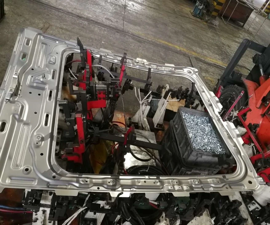
The fixture presents the frame for inspection.
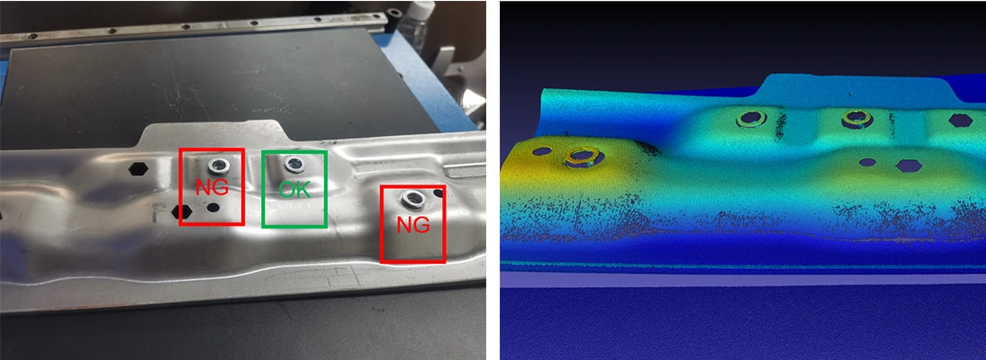
Marked rivet states are shown beside a depth representation.
Select an image to view it at full size.
Measure each rivet relative to its local frame surface
Swipe across the table to compare all columns →
| Condition | Approach to evaluate | Selection check |
|---|---|---|
| Rivet only needs to be present | Evaluate a 2D presence view. | This does not measure seating height. |
| Height or protrusion determines acceptance | Evaluate calibrated 3D profiles. | Reference the local frame surface and validate repeatability. |
| Occlusion hides one side | Assess another view or fixture arrangement. | Show complete coverage of required rivets. |
Fit the reference around the rivet, not through it
Locate the frame and expected rivet sites, then select nearby surface regions appropriate to each measurement. Exclude rivet heads, edges, holes and unreliable depth points from the reference fit. Calculate the required height relative to that local surface using the drawing's measurement definition; different definitions such as peak or fitted head level are not interchangeable.
A 3D sensor is useful when actual relative height is required. A 2D top view may establish presence and lateral placement but cannot automatically distinguish an overheight head from a normal one. Check reflective and steep surfaces for depth gaps. A missing depth value is unavailable measurement, not evidence of a low or missing rivet.
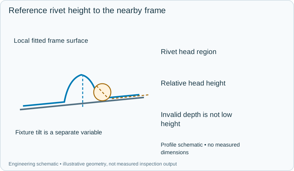
On a small screen, scroll across the diagram to inspect the labels.
Worked example: the whole frame is tilted in the fixture
In an illustrative scan, several rivets appear high in machine coordinates. Their neighbouring surface levels rise by the same amount. After valid local referencing, their relative heights remain acceptable. The fixture pose should still remain within the validated scan envelope; reference fitting is not permission to accept any orientation.
Another position contains no head where a rivet is expected, producing a presence failure. A third has a head with insufficient valid depth points because of reflection. Mark that position unmeasured and rescan under an approved arrangement or hold it for another measurement. Aggregate the frame result only after every required site has a resolved outcome. Retain per-site reference regions, valid-data status, calculated dimensions and confirmation of the frame's final handling.
Swipe across the table to compare all columns →
| Observed evidence | Inspection decision | Action and retained record |
|---|---|---|
| All absolute heights shift with frame tilt but valid local rivet-to-surface heights remain stable. | Pose change does not necessarily indicate high rivets. | Retain the local reference fits and permitted fixture pose; verify every required site and the scan envelope before accepting the frame. |
| An expected rivet site has no visible head in a valid view. | Presence failure independent of height measurement. | Record the missing site and frame identity, hold or reject the assembly and inspect the repaired site under a controlled new attempt. |
| A reflective head lacks enough valid depth points for the specified dimension. | Height unavailable, not automatically low or missing. | Store the validity mask and reference region, rescan through the approved arrangement or use the defined alternative measurement before disposition. |
Compare repeatability with an independent reference
Unload and reload the same reference parts, vary permitted fixture pose and include known height differences checked by an appropriate reference instrument. Review both measurement bias and repeatability at each site. A stable numeric result is not sufficient if it follows the wrong surface.
Keep the optical height requirement separate from rivet strength or fastening integrity. If an assembly is reworked, reidentify the frame and repeat the required rivet checks, preserving the original failed position and the rework attempt.
Swipe across the table to compare all columns →
| Challenge | What to verify |
|---|---|
| Missing rivet | Verify count and position-specific failure. |
| High or low seated rivet | Compare against the reference method. |
| Frame tilt and reload | Measure variation introduced by presentation. |
| Reflective or missing depth data | Prevent invalid measurements from becoming a pass. |
Frame variants and rivet-height limits to provide
The metal components and fabrication guide provides context for locating and checking components during assembly; rivet acceptance still depends on the relevant drawing and local height reference.
Provide the rivet map, local datums, height limits, fixture constraints and reference measurements for good and faulty assemblies.
Use the vision measurement vs cmm and gauges guide to develop the next step.
Define the wider inspection responsibility in dimensional measurement.
Develop the related acceptance requirements with assembly verification.
Use the optical and recovery challenges above when applying the architecture choices in vision-system comparison guide.
Scope and budget
Use the assembly verification scope and cost factors to scope the assembly station, including the added depth view and local frame reference needed for rivet height.
Testing and handover
Challenge fixture tilt, a missing rivet and invalid depth data during the testing and handover process.