Application guide by addaScanCompare the inspection task, imaging conditions and validation steps with your own production line.
- Inspection task
- Machined hole-feature measurement
- Decision focus
- machined hole-feature measurement
- Station planning
- Validate the edge before fitting its geometry
- Illustrative scenario
- a broken tap produces a false hole fit
Hole edges, fitted circles and component references
The application images show the physical product and imaging conditions. The engineering diagram below explains the inspection logic and recovery decisions.
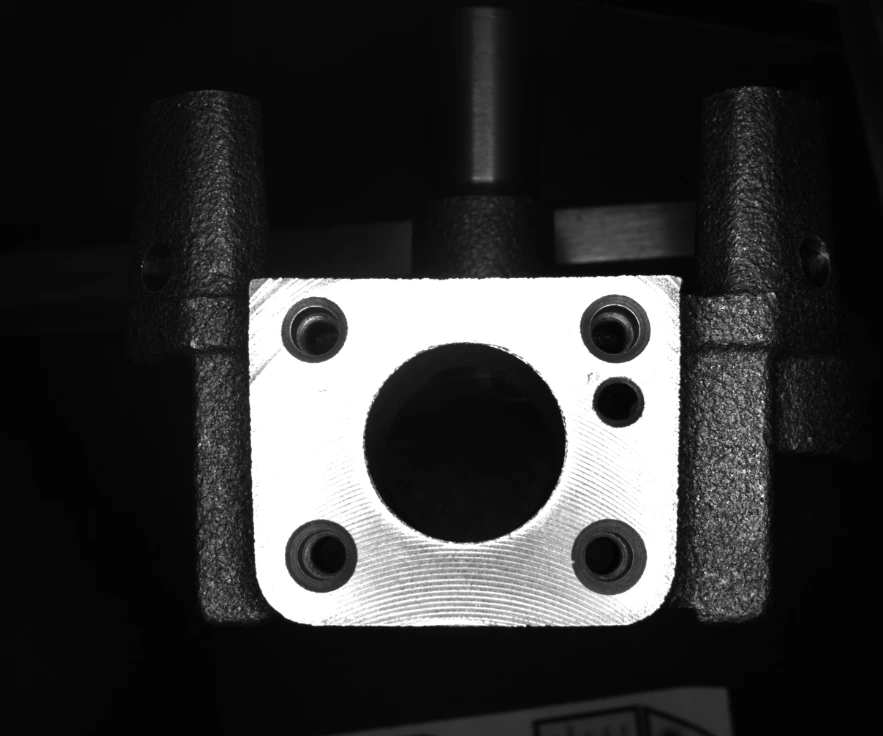
Acquired image used in the documented hole-inspection trials.
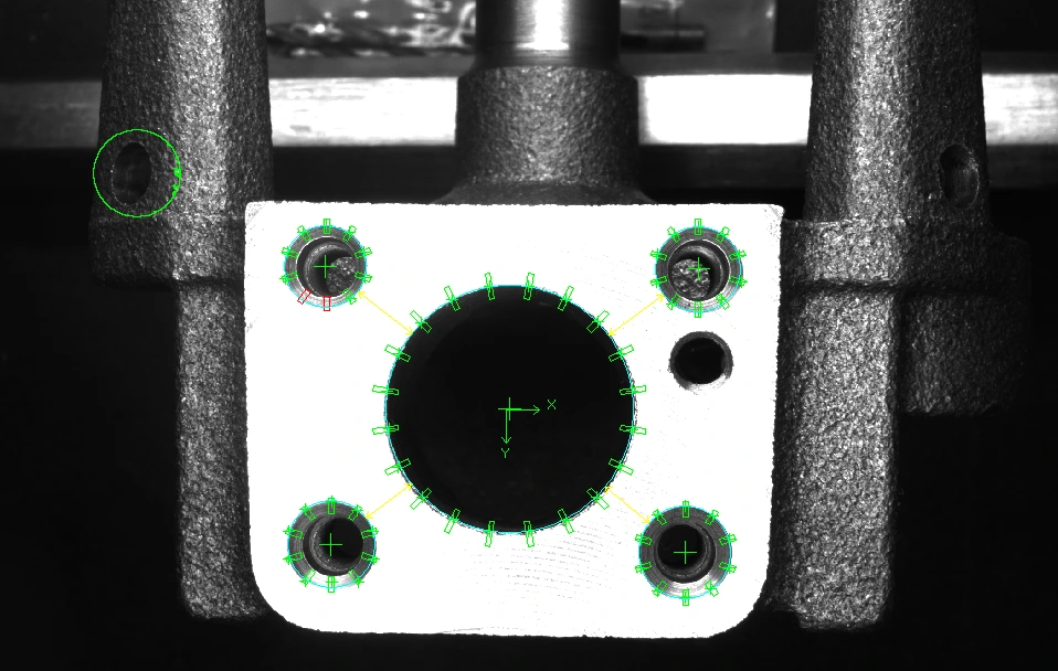
Original circles and centre references from the processed inspection image. They illustrate the measured features, not a transferable tolerance guarantee.
Select an image to view it at full size.
Define which physical edge represents the hole dimension
Swipe across the table to compare all columns →
| Condition | Approach to evaluate | Selection check |
|---|---|---|
| Presence or visible obstruction | Evaluate contrast and region checks. | A dark area is not proof of full bore depth. |
| Diameter and centre spacing | Evaluate calibrated 2D edge measurement. | Test loading variation and correlate with a reference gauge. |
| Depth or hidden bore condition | Assess another view or measurement method. | A front image cannot establish unseen internal geometry. |
Validate the edge before fitting its geometry
Locate the workpiece datum, calibrate the measurement arrangement and define the required hole regions. Determine whether the visible boundary is the opening at the specified plane or a chamfer edge. Telecentric optics may help reduce magnification changes over a controlled depth range; they do not make an inaccessible internal bore visible.
Assess edge coverage and residuals before accepting a fitted circle or centre. A fit based on a small surviving arc can appear precise while being poorly constrained. Set the permitted missing-edge behaviour using real samples and the measurement uncertainty required by the drawing. Side holes need a suitable view of their own, and deeper bore features may need a different instrument.
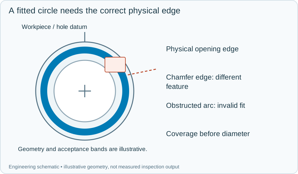
On a small screen, scroll across the diagram to inspect the labels.
Worked example: a broken tap produces a false hole fit
In an illustrative part, residual tooling obscures part of a hole. The software fits a circle to the remaining bright boundary and returns a number. The edge-coverage test fails because the required physical contour is not established. Mark the hole obstructed or unmeasurable and hold the part; do not use the fitted value as evidence of diameter compliance.
After authorised removal of the obstruction, repeat the measurement on the identified part. Confirm the correct edge plane and record the new result as a separate attempt. A complete but oversized opening should fail the dimensional rule, while an incomplete view should fail measurement validity. Keep those reasons separate. Aggregate hole diameter and centre-spacing results only when their underlying references are valid, and retain the datum, sampled edge points and reference-instrument comparison with the inspection record.
Swipe across the table to compare all columns →
| Observed evidence | Inspection decision | Action and retained record |
|---|---|---|
| A circle fit uses only a small surviving arc around an obstruction. | Measurement validity fails even when a diameter is returned. | Keep sampled edges and fit coverage, hold the component and repeat after authorised obstruction removal with the correct physical edge selected. |
| A complete edge corresponds to the chamfer rather than the drawing's measurement plane. | Wrong feature selection; the numeric result is not acceptance evidence. | Retain the datum and image, correct the measurement region and verify agreement with the appropriate reference instrument. |
| Hole centres are valid but a required side-hole view is absent. | Only the observed dimensions are established. | Mark the missing requirement explicitly, obtain the assigned view or measurement and combine results under the same component event. |
Challenge the measurement chain rather than one nominal part
Use acceptable and unacceptable dimensions established by an appropriate reference method, chamfer variation, burrs, oil, partial obstruction and permitted loading variation. Check repeated loading as well as repeated images without movement.
Vision can measure the visible features qualified for the optical setup. It does not establish deep-bore geometry, thread function or all drawing requirements from one top view. Assign those requirements to the necessary gauges or additional measurements and make unavailable optical results explicit in the part disposition.
Swipe across the table to compare all columns →
| Challenge | What to verify |
|---|---|
| Known diameters near the acceptance boundary | Compare measurements with the agreed reference. |
| Reloaded and tilted components | Measure repeatability under real fixturing. |
| Missing hole or retained tap | Verify a distinct failure without a misleading fitted circle. |
| Surface-finish variation | Check that illumination preserves the physical edge. |
Hole drawings, datums and sample parts to provide
Use the machining inspection guide to relate hole measurement to datums, fixturing and the part's wider drawing requirements.
Provide the drawing, datums, tolerances, reference measurements, allowed part pose and examples of missing or obstructed holes.
Use the vision measurement vs cmm and gauges guide to develop the next step.
Define the wider inspection responsibility in dimensional measurement.
Develop the related acceptance requirements with machined hole feature inspection.
Use the optical and recovery challenges above when applying the architecture choices in vision-system comparison guide.
Scope and budget
Review datum selection, measurement coverage and part presentation with the machined hole feature inspection scope and cost factors.
Testing and handover
Use the testing and handover process to compare camera results with reference measurements and agree the treatment of unclear hole edges.