Application guide by addaScanCompare the inspection task, imaging conditions and validation steps with your own production line.
- Inspection task
- Battery top-cover weld inspection
- Decision focus
- battery top-cover weld inspection
- Station planning
- Register the weld path before classifying its appearance
- Illustrative scenario
- a bright spot near a corner
Visible weld-mark regions on a battery top cover
The application images show the physical product and imaging conditions. The engineering diagram below explains the inspection logic and recovery decisions.
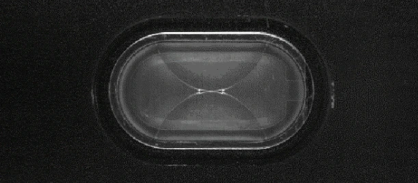
Selected weld region from the inspection image; the region is shown without the software text labels.
Select an image to view it at full size.
Assign each visible weld fault to a cover region
Swipe across the table to compare all columns →
| Condition | Approach to evaluate | Selection check |
|---|---|---|
| Stable and distinct weld geometry | Evaluate explicit position and continuity rules. | Test background changes before adding complexity. |
| Several visually similar defect classes | Compare trained segmentation on agreed labels. | Review confusing normal texture with the process owner. |
| Weld extends around several faces | Evaluate indexed views or controlled motion. | Demonstrate coverage between adjacent views. |
Register the weld path before classifying its appearance
Locate the cover from stable geometry, then place the weld regions relative to that reference. Include the allowed path variation without letting a wide region absorb unrelated edges or reflections. Keep accepted weld ripples as explicit normal examples, especially where they resemble the suspected fault.
Directional lighting can reveal raised spatter but may exaggerate normal ripples; diffuse illumination may stabilise broader surface appearance while reducing relief contrast. Compare registered views on the same fault samples. A classifier suits repeatable region categories; localisation or segmentation is more useful when the operator needs the extent and position of a visible anomaly. Select the tool from the required decision and evidence, not merely from the availability of a deep-learning option.
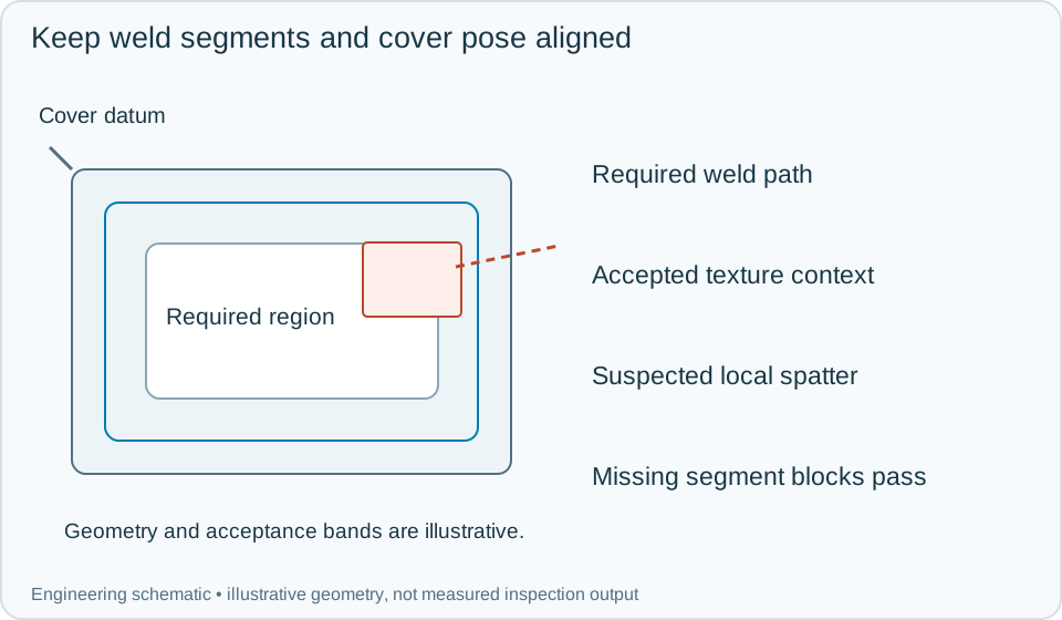
On a small screen, scroll across the diagram to inspect the labels.
Worked example: a bright spot near a corner
In an illustrative cover image, a bright spot lies in a corner region. First confirm that the weld region follows the actual cover pose. If the region is displaced onto a nearby shiny edge, invalidate localisation and reacquire after correcting presentation. Do not train that registration error as normal welding.
With valid registration, compare the spot against accepted weld texture under the qualified light views. A local feature meeting the visible-spatter rule fails that region; an ambiguous feature is retained for the agreed review route. If another required segment is hidden, the cover remains incompletely inspected even when every observed segment passes. Aggregate regional decisions only after all required views are present, then bind the cover-level result and reject confirmation to the same part event.
Swipe across the table to compare all columns →
| Observed evidence | Inspection decision | Action and retained record |
|---|---|---|
| A suspected spot lies on an accepted weld ripple after correct regional location. | Evaluate with hard normal samples before declaring a fault. | Retain the local crop with surrounding weld context and the qualified illumination view; do not weaken every region's threshold together. |
| A visible local anomaly meets the agreed spatter or discontinuity criterion in a valid region. | That weld segment fails the external appearance rule. | Record the segment identifier, location and image, combine with other regional results and confirm the affected cover's rejection. |
| The cover passes observed regions but a corner is hidden by geometry. | Required weld coverage incomplete. | Hold the cover and recover the missing view or change the inspection arrangement. Do not infer internal weld integrity from external views. |
Validate hard normal samples and missing coverage
Include accepted ripple patterns, normal corner transitions, known visible faults, part displacement and a missing view. Record the region, reference transform, image and reason for rejection or uncertainty. Review repeated false alarms by region rather than weakening a threshold over the whole cover.
Visible weld appearance cannot establish internal penetration, sealing or mechanical strength. Keep those requirements assigned to their relevant process or test evidence. The vision result should state which external regions were observed and which appearance rules were applied.
Swipe across the table to compare all columns →
| Challenge | What to verify |
|---|---|
| Normal texture resembling an explosion mark | Measure false rejects. |
| Fault in each inspection zone | Verify coverage and correct region assignment. |
| Position and reflection changes | Confirm the model is not relying on one background. |
| Missed or repeated camera step | Hold the part when the view set is incomplete. |
Top-cover welds and surface variations to test
Provide weld-zone drawings, acceptable and defective examples by zone, presentation motion and the required independent weld tests.
Use the machine vision lighting guide to develop the next step.
Define the wider inspection responsibility in surface defect detection.
Translate these view and interface requirements into equipment choices with hikrobot visionmaster.
Use the optical and recovery challenges above when applying the architecture choices in vision-system comparison guide.
Scope and budget
The vision system cost guide provides general imaging and integration factors; weld-zone coverage and independent integrity tests must be scoped separately.
Testing and handover
Use the testing and handover process to agree class labels by weld zone and the follow-up action for an uncertain surface result.