Application guide by addaScanCompare the inspection task, imaging conditions and validation steps with your own production line.
- Inspection task
- Battery insulation-film defects
- Decision focus
- battery insulation-film defects
- Station planning
- Keep sampling, tiling and coordinates connected
- Illustrative scenario
- one pinhole crosses two processing tiles
Small film defects within a much larger inspection image
The application images show the physical product and imaging conditions. The engineering diagram below explains the inspection logic and recovery decisions.
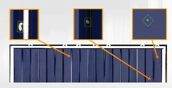
Local defect enlargements above the long film image illustrate the difference in scale.
Select an image to view it at full size.
Preserve tiny film defects through the image pipeline
Swipe across the table to compare all columns →
| Condition | Approach to evaluate | Selection check |
|---|---|---|
| Large unused borders | Crop the background first. | Keep film wander inside the retained region. |
| Sparse tiny defects | Evaluate native-resolution tiles. | Test tile edges and reconstruction of defect positions. |
| Lower-resolution processing | Measure what downsampling removes. | Reject the optimisation if required defects disappear. |
Keep sampling, tiling and coordinates connected
Choose the image scale from the smallest defect that must remain distinguishable under real contrast and motion. Crop to the valid film area without excluding edge defects required by the specification. If processing uses tiles, overlap them enough to preserve the necessary defect context and test defects that straddle their boundaries.
Merge overlapping detections in original-image coordinates before converting them to material coordinates. Otherwise one defect may be counted twice or its position may jump between tiles. A line-scan arrangement can suit continuous web coverage; an area camera may suit discrete pieces or indexed motion. The choice depends on exposure, motion synchronisation and field coverage, not simply on a higher advertised pixel count.
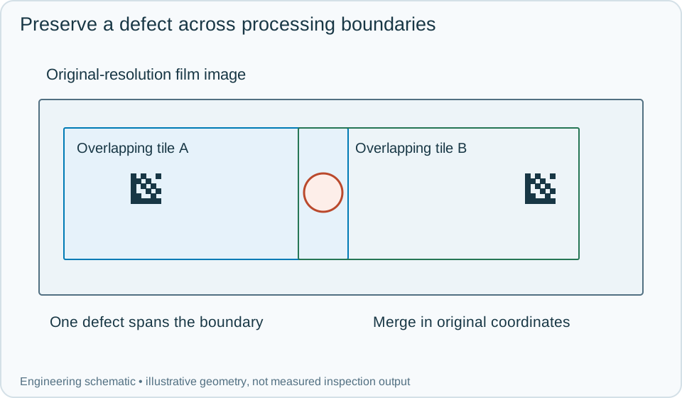
On a small screen, scroll across the diagram to inspect the labels.
Worked example: one pinhole crosses two processing tiles
In an illustrative image, a small pinhole lies at the edge of a processing tile. Without overlap, each crop contains only part of it and neither produces a reliable decision. An overlapping extraction preserves the complete feature in at least one crop. Merge any duplicate detections before assigning the event a single material location.
Compare this with reducing the whole frame: the pinhole can disappear into background pixels even though the full original image contained usable evidence. Keep original-resolution challenge crops to expose that loss. If an image line or frame is missing, mark the corresponding material interval as uninspected. The downstream handling rule should contain that interval, including position uncertainty, rather than assume an absence of detections means good film. Verify that the indicated defect position maps to the correct physical segment before releasing a roll record.
Swipe across the table to compare all columns →
| Observed evidence | Inspection decision | Action and retained record |
|---|---|---|
| A small defect straddles two tiles and only a partial shape appears in each non-overlapping crop. | Processing partition can remove required defect context. | Test overlapping extraction on the original image, retain tile coordinates and verify merged detections before calculating material position. |
| Two overlapping tiles detect the same physical flaw. | One defect event with multiple observations. | Merge in original-image coordinates, preserve supporting crops and map the single defect extent to the downstream material record. |
| The original image contains the flaw but a reduced processing input does not. | Input sampling invalidates the intended detection coverage. | Retain original and reduced images, revise the processing scale and repeat boundary and smallest-defect trials across the full pipeline. |
Validate the pipeline at its weakest boundaries
Place known defects near the film edge, crop edge and tile overlap, and repeat at different web positions. Preserve original images, tile coordinates, merged results and encoder positions. Check normal texture and contamination separately to understand false alarms.
After a resolution, lens or image-processing change, repeat the full path. A model can retain the same settings while its input sampling changes enough to invalidate the previous defect coverage.
Swipe across the table to compare all columns →
| Challenge | What to verify |
|---|---|
| Smallest required defects | Verify visibility before and after preprocessing. |
| Dust and benign highlights | Measure false rejects independently. |
| Defect across tile boundary | Confirm complete detection and a single record. |
| Long continuous production | Monitor memory, dropped lines and result latency. |
Insulation-film variations to include in a trial
Provide film width, motion, smallest defects, normal dust policy, image dimensions and the available decision distance.
Use the machine vision lighting guide to develop the next step.
Define the wider inspection responsibility in surface defect detection.
Define the wider inspection responsibility in web line scan.
Use the optical and recovery challenges above when applying the architecture choices in vision-system comparison guide.
Scope and budget
Use the vision system cost guide for general camera, lighting and data-handling factors; film width, small-defect detail and tracking need a specific scope.
Testing and handover
Include lost web position, changing texture and material handling after a defect in the testing and handover process.