Application guide by addaScanCompare the inspection task, imaging conditions and validation steps with your own production line.
- Inspection focus
- Adhesive entering a motor clearance
- Primary theme
- Surface defect detection
- Decision evidence
- Clearance keep-out zone
- Trial priority
- Continuous bead with small intrusion
Check both the bead path and regions that must remain clear
The original English schematic explains the observable features and the proposed decision. The tables below set out the conditions to test on your own line.
Swipe across the diagram to see all details →
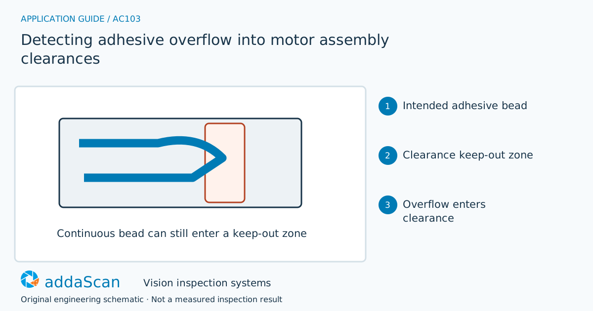
A continuous adhesive bead can still fail by entering a required clearance. Inspect the bead and the no-adhesive region independently, then recheck both after cleaning. Original schematic.
Select an image to view it at full size.
Define keep-out zones from the assembly datum
Locate the component features that establish the functional gap, then map the permitted adhesive region and keep-out region. Reflection and translucent adhesive may require different illumination from the surrounding metal. An area threshold over the whole image can miss a small but critical intrusion. If the limit concerns height as well as plan position, test a suitable profile method rather than inferring thickness from brightness.
Create a part-relative map of required adhesive and forbidden adhesive. A bead can be continuous and correctly centred over most of its length while a small spur enters a rotating or mating clearance. The inspection therefore needs a no-adhesive region as well as a bead-presence or width rule. Define the clearance boundary from the product requirement rather than from an arbitrary image margin.
Locate the component before applying those regions. Clear adhesive on reflective metal can disappear or resemble a highlight; a visible path does not prove that all overflow is observable. Test the worst qualified materials and surface finishes, and use an unresolved result where the boundary cannot be seen. Any additional profile or contrast method needs its own material feasibility evidence.
Choose geometry evidence for the actual adhesive surface
Swipe across the table to compare all columns →
| Approach | Useful when | Limit or integration responsibility |
|---|---|---|
| Bead continuity | Missing adhesive along the intended path | Does not protect nearby functional clearances. |
| Bead plus keep-out inspection | Position and overflow constraints | Needs registered boundaries and appropriate evidence for any height limit. |
Two-dimensional appearance can establish path and intrusion where contrast is qualified. Height evidence may support relief or bead-section checks, but must retain validity at the clearance boundary. Compare methods using both a correct continuous bead and a small forbidden intrusion, rather than only obvious bead breaks.
A continuous bead can still intrude into a clearance
Illustrative scenario: the bead is continuous, but a small tongue extends into the defined clearance. Hold the assembly on intrusion evidence.
After controlled cleaning or rework, re-register the part and inspect the entire keep-out region, retaining the original image. Release only when the required clearance is visibly resolved; a hidden edge or ambiguous transparent deposit remains open for further assessment.
After removing excess adhesive, check both the cleared region and the required bead, because cleaning may create a gap. Keep the part and rework identity. If surfaces are joined before the disputed region is observed, resolve the inspection through the agreed independent process instead of assuming the overflow disappeared.
Challenge small overflow and clear adhesive on metal
Swipe across the table to compare all columns →
| Challenge sample or event | Expected behaviour to establish | Evidence to retain |
|---|---|---|
| Continuous bead with small intrusion | Reject the functional-zone violation. | Part datum, intended bead path, forbidden-clearance map, small intrusion image/profile and separate bead/clearance results. |
| Reflective metal and clear adhesive | Prove contrast using actual deposits. | Adhesive and metal references, lighting/profile validity, ambiguous boundary and qualified reacquisition or hold result. |
| Cleaned assembly | Recheck the whole keep-out zone and preserve rework evidence. | Original intrusion, cleaning action, remaining bead geometry, newly clear region and final complete reinspection. |
Include a continuous bead with small intrusion, an apparently clear region with poor optical evidence and a cleaned part with a new bead gap. Retain results for both required and forbidden regions. Curing, adhesion and motor performance are separate requirements.
Bead geometry does not establish bond strength
Visible adhesive geometry does not establish cure, bond strength or chemical compatibility.
Define the mating clearances before specifying bead inspection
Share permitted photos or drawings, plus details of bead specifications, keep-out drawings, adhesive sample examples and assembly/rework conditions. Agree any physical sample arrangements after the initial assessment.
Glue bead inspection for adhesive and sealant defines visible bead geometry, including width, path and profile height where appropriate. Include clearance-region visibility and post-cleaning checks in the proposed scope.
Automotive glue-bead inspection covers automotive bead continuity and position. The motor task adds a specific no-adhesive clearance that can fail even when continuity passes.
Review the indicative station budget and exclusions. The bead-inspection budget concerns visible geometry; bond strength, motor performance and a robot supplied for handling are not implied.
Compare lighting, processing, interfaces and support in the HIKROBOT and other vision solutions guide. Agree sample testing, acceptance responsibilities and handover through the delivery process.