Application guide by addaScanCompare the inspection task, imaging conditions and validation steps with your own production line.
- Task
- Short-shot inspection on moulded caps
- Decision focus
- Closure inspection
- Workflow
- Present one cap in the required orientation.
- Validation
- Normal gate and parting variation
Missing material, excess flash and an obscured cap edge
Original explanatory diagrams show the product states and inspection questions. They are schematics, not captured inspection results.
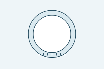
The visible edge follows the accepted profile.
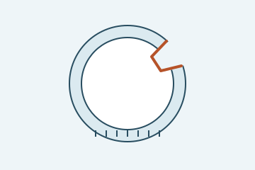
An inward gap interrupts the expected cap outline.
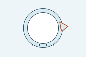
Extra material projects beyond the normal profile.
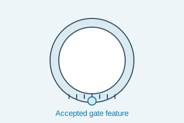
A known gate or parting feature belongs in the reference.
Select an image to view it at full size.
Distinguish a moulding short shot from an approved cap feature
Explore Closure inspection system and Surface defect detection to connect this inspection task with the wider station requirements.
Swipe across the table to compare all columns →
| Decision | Evidence to use | Rule to agree |
|---|---|---|
| Missing material | Compare inward edge deviations with the accepted profile. | Check the feature is actually visible. |
| Excess material | Evaluate outward deviations separately. | Do not confuse flash with the normal gate. |
| Recipe match | Use the correct cap family and orientation. | Hold an unrecognised part rather than forcing a match. |
Compare the right contour in the right orientation
Locate a stable moulded feature if the acceptance map is not rotationally symmetric. Define the allowed contour around that reference and exclude only the features explicitly permitted by the drawing. Backlighting can expose external missing material, but internal ribs or thread features may need another view.
A tolerance band is a geometric acceptance concept, not a substitute for the actual drawing limits. Validate glare, translucency and focus because they can move the apparent edge. A trained appearance method may help with complex internal features, while a clear silhouette often supports simpler contour checks. Choose each tool for the region it can observe.
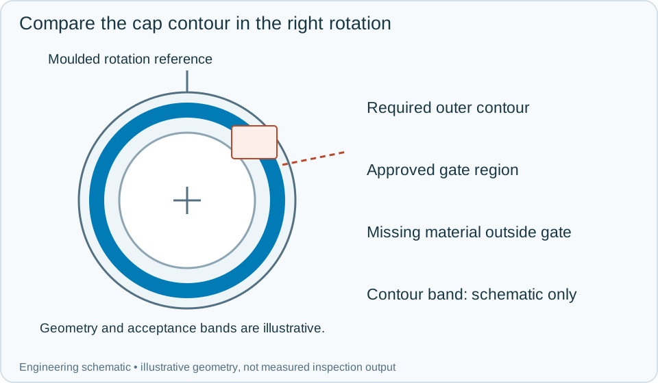
On a small screen, scroll across the diagram to inspect the labels.
Swipe across the table to compare all columns →
| Approach | Useful when | What to validate |
|---|---|---|
| Backlit contour | Outer-edge completeness is the target. | Define how overlapping parts are handled. |
| Reflected-light view | Surface or internal detail must be visible. | Check glare and resin colour variation. |
| Multiple views | Top, side and underside features have separate requirements. | Combine results by individual cap. |
Worked example: a normal gate is flagged as missing material
In an illustrative cap, the region map is rotated relative to the moulded reference. The expected gate falls into a region that assumes a smooth edge, causing a false failure. Correct the location and orientation chain before widening the contour allowance.
A second cap has a genuine missing segment in a required smooth region. Preserve the local contour deviation and reject it. A third has a blurred edge caused by poor presentation; return invalid view and reimage under the approved setup. Merge external and internal checks only when all required views belong to the same cap. If a mould-cavity identifier is available from the process, retain it with the defect; do not infer a cavity number from a generic short-shot shape.
Swipe across the table to compare all columns →
| Observed evidence | Inspection decision | Action and retained record |
|---|---|---|
| A contour difference lies at the approved gate after valid angular location. | Evaluate as permitted design geometry, not automatic missing material. | Retain the cap-reference transform and gate region. Verify the remaining required contour independently rather than widening all edge limits. |
| Missing material interrupts a required smooth edge with a sharp valid silhouette. | Short-shot candidate meeting the agreed contour criterion. | Keep the local edge evidence, reject the cap and attach available mould or cavity process identifiers without inferring them visually. |
| A translucent edge changes position with glare and cannot be located repeatably. | Invalid edge measurement; physical missing material is unproven. | Hold or reacquire with qualified illumination. Preserve the original image and compare a reference cap before restoring the recipe. |
How should a suspected short shot be handled?
- 01Separate and locatePresent one cap in the required orientation.
- 02Expose the featureUse the view selected for the target defect.
- 03Compare contoursDistinguish missing, extra and accepted features.
- 04Reject and recordKeep the fault and cap identity together.
Locate the cap before comparing its edge, but do not let alignment erase a real shape error. Define the rotational datum where asymmetric details matter. Preserve the recipe and cavity identity when that information is available, so a defect trend can be investigated without inventing a cavity association from appearance alone.
Challenge normal features beside the smallest required defect
Include gates at different rotations, approved flash limits, known missing-material samples and different plastic colours. Verify repeatable edge placement with a reference sample after lighting or lens maintenance.
A visible contour pass does not establish hidden thread geometry or closure performance. Keep the unobserved requirements assigned to the relevant additional views or functional tests.
Swipe across the table to compare all columns →
| Challenge | What the trial should establish |
|---|---|
| Normal gate and parting variation | Confirm acceptable caps are not rejected as flash. |
| Small confirmed short shots | Check visibility at all allowed rotations. |
| Translucent and opaque resin | Verify each lighting and recipe combination. |
| Double-fed or tilted caps | Check the invalid-presentation response. |
What a visible cap inspection cannot prove
A visible edge defect may be consistent with a short shot, but the image does not establish the moulding-process cause. Torque, material properties and leak performance need separate tests. A contour check also needs a stated viewing limit; defects behind another surface remain outside that view.
Use Short shots in injection-moulded closures to develop the related acceptance and integration questions for your trial.
Good caps and moulding defects to compare
Use the plastics and packaging guide to place cap inspection after moulding and before defects are hidden by subsequent assembly.
Supply good caps from the normal moulding range, confirmed short shots and flash, underside defects, resin variants and the approved drawings or defect catalogue.
Use the optical and recovery challenges above when applying the architecture choices in HIKROBOT and other vision solutions comparison.
Scope and budget
The closure inspection system scope and cost factors helps scope cap presentation and the views needed for incomplete rims, threads or bridges.
Testing and handover
Use the testing and handover process to distinguish acceptable moulding variation from a short shot and to confirm suspect-cap handling.