Application guide by addaScanCompare the inspection task, imaging conditions and validation steps with your own production line.
- Inspection task
- Battery electrode coating inspection
- Decision focus
- battery electrode coating inspection
- Station planning
- Choose defect evidence before choosing the model
- Illustrative scenario
- an apparent clean interval contains missing frames
Visible coating damage and electrode scratches
The application images show the physical product and imaging conditions. The engineering diagram below explains the inspection logic and recovery decisions.
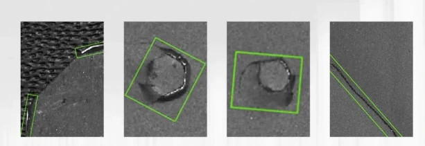
Different surface features are marked in the inspection details.
Select an image to view it at full size.
Locate coating defects on both sides of the electrode web
Swipe across the table to compare all columns →
| Condition | Approach to evaluate | Selection check |
|---|---|---|
| Distinct missing coating | Evaluate contrast and connected-region rules. | Challenge acceptable coating texture and edges. |
| Low-contrast scratches or several textures | Evaluate trained segmentation after optical trials. | Keep subtle faults in an independent test set. |
| Both sides required | Provide verified coverage of each surface. | Do not infer hidden-side quality from the visible face. |
Choose defect evidence before choosing the model
A missing coating region may change broad reflectance, whereas a shallow scratch can be visible only under a useful lighting direction. Compare acceptable texture, coating transitions and known faults at the intended image scale. Detection or segmentation is valuable when the handling decision needs an extent; classification alone can suit a controlled small region with one defined disposition.
For double-sided inspection, calibrate the two views to a shared material coordinate while retaining the side identifier. Camera spacing and web travel introduce offsets. Encoder tracking must account for those offsets before comparing apparent defect positions. Do not merge coincident coordinates from opposite surfaces into one unexplained result.
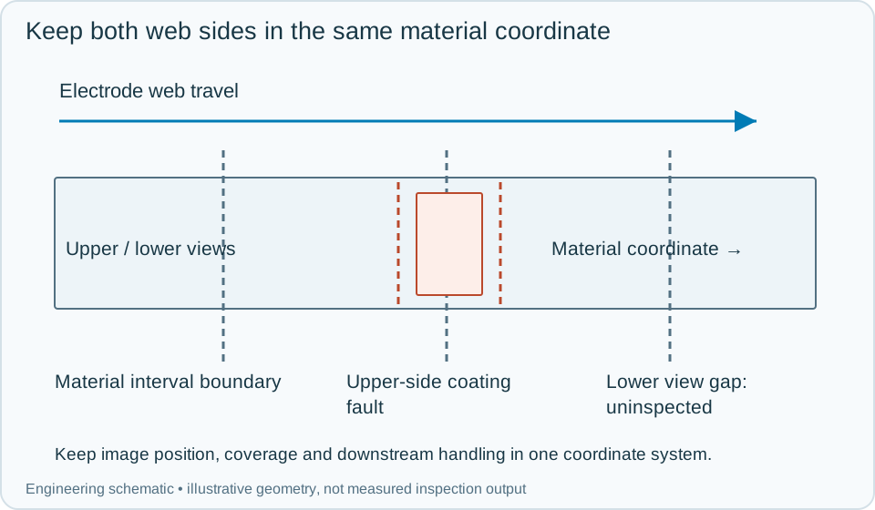
On a small screen, scroll across the diagram to inspect the labels.
Worked example: an apparent clean interval contains missing frames
In an illustrative run, the upper surface records a local coating gap while the lower view records no fault at the corresponding position. Keep the upper-side defect and its extent; absence on the opposite surface does not cancel it. Map the affected interval to the downstream handling record with the established position uncertainty.
Later, the lower camera drops frames across a splice. That interval is uninspected, even if the upper surface has complete acceptable images. Flag the missing lower coverage and contain or reinspect the affected material under the agreed rule. After a web break or encoder reset, establish a new coordinate reference before returning to normal release. Store the side-specific images, interval coverage, roll identity and disposition so a cut piece can be traced to the appropriate inspection evidence.
Swipe across the table to compare all columns →
| Observed evidence | Inspection decision | Action and retained record |
|---|---|---|
| A coating gap is located on the upper surface while the lower surface looks normal at the same material coordinate. | Upper-side defect remains actionable. | Keep side and interval identifiers, apply the agreed containment rule and verify marking or isolation of the corresponding downstream material. |
| Lower-side frames are missing through a splice while upper-side acquisition continues. | Required double-sided coverage is incomplete. | Record the uninspected side and interval, contain or reinspect it and restore coordinate continuity before normal release resumes. |
| Normal coating texture triggers a fine-grained class that does not change any handling decision. | Review whether classification adds useful evidence beyond detection. | Compare accepted texture and actionable defects, retain location masks and simplify the decision only after validating missed-defect and false-reject behaviour. |
Validate normal texture and coordinate interruptions together
Challenge low-contrast scratches in different directions, accepted coating texture, both web edges, splices and interrupted acquisition. Verify that the physical marked or isolated length agrees with the image location; a good defect detector with incorrect material tracking still produces unusable containment.
Retain original images around defects and coverage gaps, not just a roll-level pass flag. Surface appearance supports visible coating inspection; it does not by itself establish electrochemical performance or hidden material properties.
Swipe across the table to compare all columns →
| Challenge | What to verify |
|---|---|
| Low-contrast scratches | Confirm they remain visible at the selected line speed. |
| Normal coating variation | Measure false rejects separately by face. |
| Edge and splice regions | Define inspection masks and exceptions explicitly. |
| Encoder or image loss | Identify the uninspected material interval. |
Electrode coating samples and web data to provide
Provide both electrode surfaces, defect dimensions and classes, normal texture, material speed and the downstream handling distance.
Use the web line scan guide to develop the next step.
Define the wider inspection responsibility in surface defect detection.
Use the optical and recovery challenges above when applying the architecture choices in vision-system comparison guide.
Scope and budget
Use the vision system cost guide for general imaging and integration factors; electrode surface coverage and web-handling requirements need an application-specific scope.
Testing and handover
Agree defect classes, position tracking and uncertain-boundary handling in the testing and handover process.