Application guide by addaScanCompare the inspection task, imaging conditions and validation steps with your own production line.
- Inspection task
- Automotive control print inspection
- Decision focus
- automotive control print inspection
- Station planning
- Keep the part datum independent of the artwork
- Illustrative scenario
- the icon is correct but a stroke is missing
Printed symbol outlines on an automotive control
The application images show the physical product and imaging conditions. The engineering diagram below explains the inspection logic and recovery decisions.
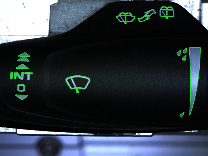
Original inspection view of the automotive control, retaining symbol outlines.
Select an image to view it at full size.
Locate the control before judging its printed symbol
Swipe across the table to compare all columns →
| Condition | Approach to evaluate | Selection check |
|---|---|---|
| Missing or extra strokes | Evaluate aligned artwork comparison. | Include acceptable screen-print variation. |
| Print position | Reference the physical part geometry. | Do not align away the fault using the print itself. |
| Colour difference | Use controlled colour imaging and a reference method. | Test lighting drift and surface gloss. |
Keep the part datum independent of the artwork
First locate stable moulded geometry such as the control perimeter or a keyed feature. Select the expected symbol from the production recipe, then search for the print within the permitted area. Measuring the print after aligning solely to that print would make an offset symbol appear centred. Rotation that is acceptable for transport should be removed using the part reference; rotation of the symbol relative to the part remains a measured defect.
A template can be effective for a stable icon and limited variation. If texture, gloss or approved colour changes produce large image differences, evaluate illumination and feature-based or trained appearance checks before lowering the acceptance threshold. Keep the placement measurement independent whichever recognition method is chosen. A correctly classified icon is not evidence that its strokes or position meet the drawing.
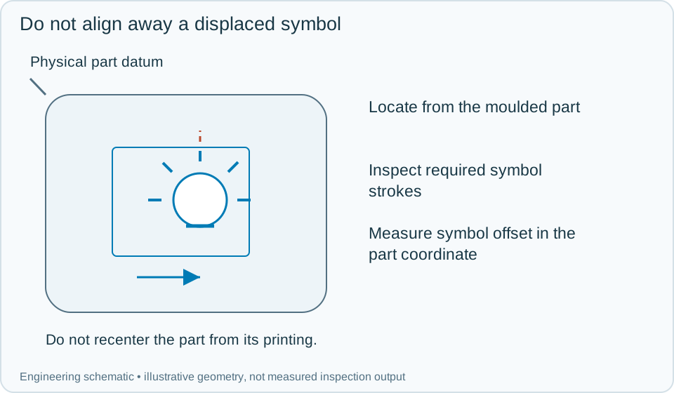
On a small screen, scroll across the diagram to inspect the labels.
Worked example: the icon is correct but a stroke is missing
In an illustrative button inspection, the outer contour locates correctly and the recipe expects a lamp symbol. The main outline matches, but one short ray is absent. A broad classification score could still identify the icon as a lamp. Compare the required stroke regions with the approved print reference and retain the local missing-stroke evidence. The part fails print completeness even if identity and centring pass.
Next inspect a complete icon shifted towards the edge. The part datum remains unchanged, so the relative symbol position fails independently. Finally, present an approved lower-gloss sample. If its geometry and strokes are intact but overall brightness changes, diagnose the imaging response before treating the darker image as missing ink. Each result should retain the recipe, part-reference transform, print-region evidence and separate identity, completeness and placement decisions. Route failed parts to the reject stream and confirm their removal before counting them as contained.
Swipe across the table to compare all columns →
| Observed evidence | Inspection decision | Action and retained record |
|---|---|---|
| The expected icon is recognised but one required ray or stroke is missing. | Identity passes; print completeness fails. | Retain the physical part reference and local missing-stroke region, reject the control and confirm its removal from the accepted stream. |
| The complete icon is displaced relative to independently located moulded geometry. | Print placement failure. | Record both datums and the relative displacement. Do not align from the artwork in a way that erases the observed error. |
| An approved gloss change shifts overall brightness while required strokes remain intact. | Imaging or accepted appearance variation, subject to validation. | Compare reference samples under the qualified light, preserve actual defects in the evaluation set and control any recipe adjustment. |
Verify a recipe change without teaching away a defect
Use approved artwork versions and physical good samples as controlled references. Include a neighbouring model with a similar symbol, rotated parts, faint acceptable ink and deliberately incomplete strokes. A change to the matching tolerance must not also widen the allowed placement region unless that drawing requirement changes.
After maintenance, recheck a known displaced print against the independent part datum. If it now passes, inspect the alignment chain before adding training images. Keep rejected samples traceable to their mould or print batch where that information is available; do not infer a cavity identity from image appearance alone.
Swipe across the table to compare all columns →
| Challenge | What to verify |
|---|---|
| Missing section of an icon | Confirm completeness rather than mere symbol presence. |
| Correct artwork on the wrong variant | Compare with the active part reference. |
| Shifted print | Measure relative to the component datum. |
| Normal shade and gloss variation | Record false rejects on acceptable parts. |
Control symbols and print faults to provide
Provide approved artwork, component datums, acceptable shade samples, print faults and the product-selection signal.
Use the web line scan guide to develop the next step.
Define the wider inspection responsibility in label print inspection.
Define the wider inspection responsibility in surface defect detection.
Use the optical and recovery challenges above when applying the architecture choices in vision-system comparison guide.
Scope and budget
The vision system cost guide helps scope artwork recipes, part datums and the views needed to distinguish missing strokes from displaced printing.
Testing and handover
Include correct symbols in the wrong position and incorrect symbols in the correct position in the testing and handover process.