Application guide by addaScanCompare the inspection task, imaging conditions and validation steps with your own production line.
- Task
- Visible burr inspection on metal parts
- Decision focus
- Metal surface defect detection
- Workflow
- Identify the part and specified edge.
- Validation
- Good edges with normal machining variation
Projecting edge burrs and raised material on the face
Original explanatory diagrams show the product states and inspection questions. They are schematics, not captured inspection results.
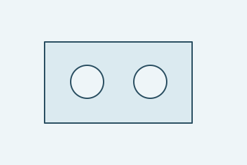
The intended contour includes normal chamfers.
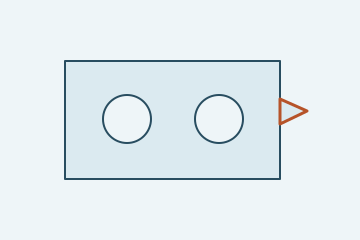
Excess material extends beyond the visible outline.
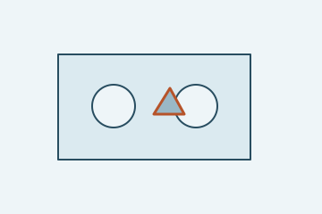
A raised feature may remain inside the silhouette.
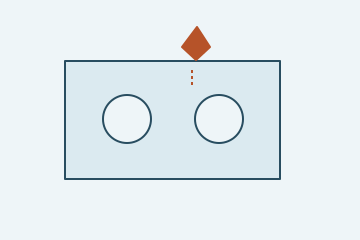
Debris can resemble an attached defect.
Select an image to view it at full size.
Specify the edge before asking the camera to find burrs
Explore Surface defect detection and Machined part burr inspection to connect this inspection task with the wider station requirements.
Swipe across the table to compare all columns →
| Decision | Evidence to use | Rule to agree |
|---|---|---|
| Edge complete and clean | Evaluate the specified visible contour. | Use accepted chamfers in the reference. |
| Excess material present | Distinguish projections from intended geometry. | Specify which direction is observed. |
| Height required | Determine whether a dimensional result is needed. | Use a suitable calibrated measurement method. |
Use silhouette and height for different questions
Backlighting can reveal material projecting beyond an outer silhouette. A burr on an internal face may not change that silhouette at all. A side view or suitable height measurement may be needed for such a feature, provided the relevant surface remains observable.
Locate the part from stable geometry and exclude only the approved chamfer or edge treatment. Validate apparent-edge changes caused by focus, reflection and pose before interpreting them as dimensional defects. A 2D contour tool may be sufficient for a stable external edge; 3D becomes useful when the acceptance question requires visible protrusion height rather than lateral outline alone.
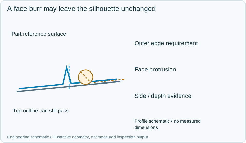
On a small screen, scroll across the diagram to inspect the labels.
Swipe across the table to compare all columns →
| Approach | Useful when | What to validate |
|---|---|---|
| Backlit silhouette | The burr projects outside the outline. | It cannot reveal every face-height defect. |
| Oblique reflected view | The target is on an exposed surface. | Challenge oil and tool marks. |
| 3D profile measurement | Burr height drives acceptance. | Validate the datum, coverage and repeatability. |
Worked example: the top silhouette is good but the face has a burr
In an illustrative part, the external contour stays within its allowed region while an upward burr sits inside the outline. The top silhouette cannot establish that requirement. The assigned side or depth view shows the protrusion and produces a separate face-burr failure.
Another feature resembles a burr but may be a loose chip. If the process permits controlled cleaning, retain the initial image, clean the identified part and repeat all affected checks. A disappearing particle is recorded as removed contamination; a persistent attached protrusion remains a burr candidate. If the required view is obscured, return incomplete inspection and hold the part. Keep the observed edge, geometric reference and physical rejection or recheck result linked to the part event.
Swipe across the table to compare all columns →
| Observed evidence | Inspection decision | Action and retained record |
|---|---|---|
| A protrusion lies inside the top outline but rises from the required face. | Top silhouette does not answer the face-burr requirement. | Use the assigned side or depth evidence, retain the geometric reference and evaluate the specified protrusion criterion independently. |
| A suspected edge feature disappears after an authorised cleaning step. | Removed contamination rather than a persistent attached burr. | Keep the original image and cleaned reinspection, re-evaluate the affected edges and record the final part disposition. |
| The apparent defect lies within an approved chamfer region and matches its qualified geometry. | Permitted edge treatment under the drawing rule. | Retain the datum and selected edge. Verify other required edges without treating this allowance as a general burr exemption. |
How should a suspected burr be routed for confirmation?
- 01Locate the datumIdentify the part and specified edge.
- 02Expose the burr directionChoose silhouette, surface or depth information.
- 03Evaluate against the limitKeep presence and height requirements separate.
- 04Route to rework or rejectRetain the exact fault location.
Locate the part using stable datums and evaluate each required edge in that coordinate system. A loose chip resting on a part may need removal and reinspection rather than the same process classification as attached excess material. Keep the decision and fault position linked to the part so a rework station knows which edge to examine.
Validate approved chamfers beside real burrs
Use reference parts with permitted edge treatments, known protrusions, loose chips and normal pose variation. Compare the optical measurement with an appropriate reference method where dimensions form part of acceptance.
Do not treat a clean visible edge as proof that all internal edges are burr-free. List the inspected edges and their views so equipment selection and customer expectations share the same coverage boundary.
Swipe across the table to compare all columns →
| Challenge | What the trial should establish |
|---|---|
| Good edges with normal machining variation | Avoid rejecting accepted geometry. |
| Burrs at different positions and directions | Find visibility blind spots. |
| Loose chips and oily surfaces | Separate contamination from attached features. |
| Part rotation or seating error | Verify datum finding and invalid-presentation handling. |
Which hidden edges need another inspection method
A two-dimensional projection does not measure every burr height or reveal hidden internal edges. If acceptance depends on sharpness, attachment or a functional interference condition, confirm the appropriate additional test. Do not turn a pixel-area threshold into a dimensional limit without calibration and a suitable geometric view.
Use Machine vision lighting to develop the related acceptance and integration questions for your trial.
Edge locations and burr samples for a trial
Use the machining inspection guide to consider deburring, cleaning and the stage at which the relevant edges remain visible.
Provide the drawings, defined burr locations and limits, good chamfers, attached burrs, loose-chip examples, oily parts and the intended fixture presentation.
Use the optical and recovery challenges above when applying the architecture choices in HIKROBOT and other vision solutions comparison.
Scope and budget
The machined part burr inspection scope and cost factors helps scope visible edge coverage and the handling needed to expose a suspect burr.
Testing and handover
Use the testing and handover process to agree a reference method for ambiguous edges and record the features outside the camera view.