Application guide by addaScanCompare the inspection task, imaging conditions and validation steps with your own production line.
- Inspection task
- Battery sealing-pin weld inspection
- Decision focus
- battery sealing-pin weld inspection
- Station planning
- Reject a bad location before interpreting the surface
- Illustrative scenario
- a suspected weld fault follows the cleaning ring
Local weld features around the sealing pin
The application images show the physical product and imaging conditions. The engineering diagram below explains the inspection logic and recovery decisions.
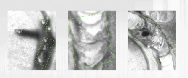
Original magnified regions retain the inspection overlays around visible weld features.
Select an image to view it at full size.
Keep the terminal, cleaning ring and weld region separate
Swipe across the table to compare all columns →
| Condition | Approach to evaluate | Selection check |
|---|---|---|
| Ring continuity and position | Evaluate geometric checks around the pin reference. | Define permitted displacement and missing segments. |
| Irregular surface faults | Evaluate segmentation with regional labels. | Include normal residue and cleaning marks. |
| New station or pin variant | Revalidate imaging and challenge samples. | A copied model is not a complete station acceptance. |
Reject a bad location before interpreting the surface
Choose locating features that survive normal cleaning and weld variation. Check the fit quality and permitted displacement before moving the inspection regions. If the terminal is only partly visible, a numerically available centre may still be unreliable. Return invalid location when the necessary geometric evidence is absent.
Use the cleaning ring as contextual information, not as an interchangeable reference for the weld itself. Illumination that makes a ring edge prominent may also magnify harmless surface marks. Compare accepted cleaning variation with real weld-related appearance faults. Where the classes overlap visually, a second illumination view or controlled review is preferable to an unsupported high-confidence label.
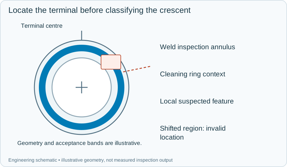
On a small screen, scroll across the diagram to inspect the labels.
Worked example: a suspected weld fault follows the cleaning ring
In an illustrative image, the defect tool highlights a crescent beside the terminal. The registered weld region has shifted onto the cleaning boundary. Correct the localisation and reacquire; the original result is an invalid-region event, not confirmed weld damage.
On a correctly located part, a similar crescent lies within the normal cleaning ring and matches approved variation. A separate raised-looking spot lies inside the required weld zone and meets the visible-spatter criterion. Keep the full terminal view and the local crop together so the operator can see why these features receive different outcomes. Hold the part when required context is missing or the feature remains ambiguous. Reinspection must use the same identified part, and the final release or rejection should preserve the earlier attempt and its reason.
Swipe across the table to compare all columns →
| Observed evidence | Inspection decision | Action and retained record |
|---|---|---|
| The suspected crescent coincides with the cleaning boundary after a shifted terminal location. | Region-placement failure is suspected. | Keep the original transform and full terminal image, correct the reference and repeat the identified part's inspection before classifying the feature. |
| A correctly placed weld region contains a qualified local spatter feature. | Visible weld-zone failure, independent of normal cleaning marks. | Record the regional context and defect crop, reject or hold the part and preserve the physical handling confirmation. |
| Terminal geometry is partly hidden and the centre fit lacks required evidence. | Location invalid; subsequent surface decisions are unavailable. | Re-present the part or use the agreed exception route. Retain the missing-reference reason rather than adding it as a normal training example. |
Make normal cleaning variation part of acceptance work
Challenge off-centre presentation, strong cleaning marks, weak terminal edges and known weld faults. Track localisation failures separately from surface-defect decisions. Otherwise a rise in false rejects may prompt unnecessary model changes when the actual problem is fixture movement.
This station evaluates visible external features in defined regions. Sealing integrity and internal weld quality require their own evidence. Store the recipe, region placement and image with the part event so any process investigation can distinguish geometry, cleaning appearance and weld-zone observations.
Swipe across the table to compare all columns →
| Challenge | What to verify |
|---|---|
| Defect in weld, inner and cleaning regions | Check regional coverage separately. |
| Normal welding dust | Measure false rejects under the agreed cleanliness policy. |
| Shifted pin image | Verify region alignment remains valid. |
| Ambiguous low-contrast fault | Define a hold or review response. |
Sealing-pin weld samples and acceptance criteria
Provide pin geometry, zone definitions, weld/cleaning variation and the criteria used by the process team.
Use the machine vision lighting guide to develop the next step.
Define the wider inspection responsibility in surface defect detection.
Translate these view and interface requirements into equipment choices with algorithm tools.
Use the optical and recovery challenges above when applying the architecture choices in vision-system comparison guide.
Scope and budget
Use the vision system cost guide to consider views, local positioning and reject handling without treating a visible weld check as a complete weld test.
Testing and handover
The testing and handover process should include surface variation around the pin and the separate evidence needed to assess weld integrity.