Application guide by addaScanCompare the inspection task, imaging conditions and validation steps with your own production line.
- Task
- Shaft diameter and step measurement
- Decision focus
- Shaft measurement
- Workflow
- Establish the axis and drawing datum.
- Validation
- Reference shafts across the size range
Measure shaft sections from the specified shoulders
Original explanatory diagrams show the product states and inspection questions. They are schematics, not captured inspection results.
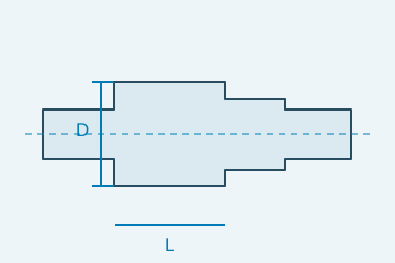
Diameter checks belong at named axial positions.
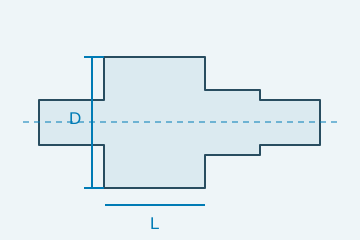
Evaluate the selected section against its limit.
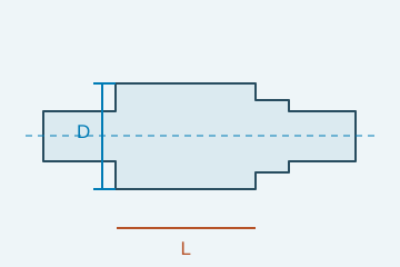
Use the specified shoulders as references.
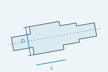
Seating changes can distort the measured profile.
Select an image to view it at full size.
Map each shaft dimension to a defined image region
Explore Fastener inspection and Machined part dimensional inspection to connect this inspection task with the wider station requirements.
Swipe across the table to compare all columns →
| Decision | Evidence to use | Rule to agree |
|---|---|---|
| Axis and seating valid | Find a reliable geometric reference. | Hold a misseated or obscured part. |
| Diameters correct | Evaluate each specified section independently. | Avoid chamfers and unintended edges. |
| Lengths correct | Measure between the defined shoulders or ends. | Use the drawing datum convention. |
Exclude transitions without hiding the required edge
Choose regions on the intended cylindrical portions and define how end faces, radii and chamfers are handled. The edge belonging to a chamfer is not automatically the edge defining the step length. Validate the optical calibration and magnification stability over the permitted part position range.
Telecentric imaging can help with controlled dimensional work, but field coverage, depth range and visible edges still constrain the task. If several views cover a long shaft, establish their common datum and transformation. Independent local measurements cannot simply be concatenated into a trustworthy overall length without that relationship.
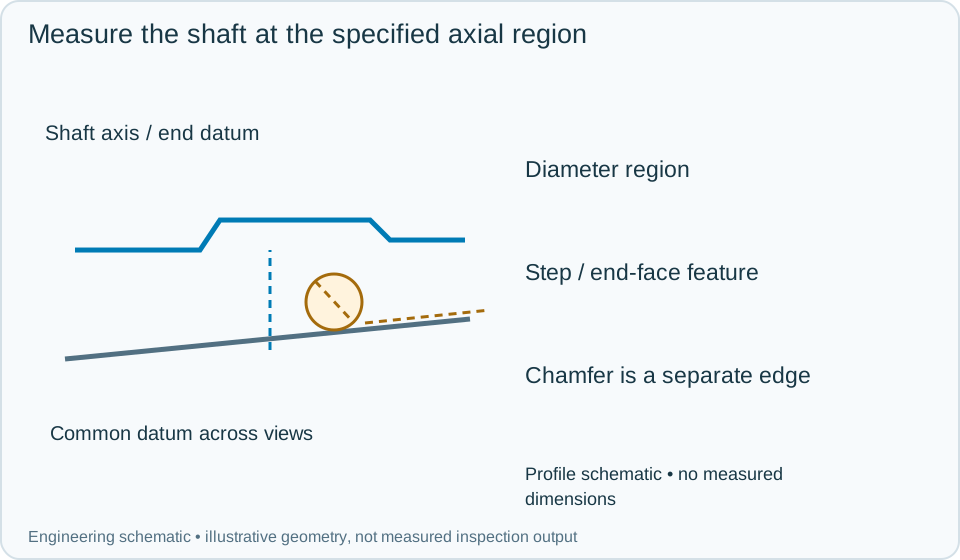
On a small screen, scroll across the diagram to inspect the labels.
Swipe across the table to compare all columns →
| Approach | Useful when | What to validate |
|---|---|---|
| Single calibrated silhouette | All required features fit a useful side view. | Check detail at the smallest tolerance. |
| Multiple measurement views | Length or geometry exceeds one suitable field. | Validate alignment and shared references. |
| Additional metrology | Roundness or functional geometry exceeds the visible profile. | Keep method responsibilities explicit. |
Worked example: a chamfer changes the apparent step position
In an illustrative shaft image, the strongest edge lies on the chamfer rather than the required end face. A generic edge search returns a plausible but incorrect step location. Restrict the measurement to the drawing-defined feature and retain the selected edge evidence for review.
At another diameter region, oil or an obstruction removes one contour. Return invalid measurement rather than calculating a width from a guessed edge. Reimage the same part after the approved recovery step, then compare valid dimensions with the specified limits. If a multi-view reference is missing, hold the dimensions that depend on that reference. Preserve the per-feature results and physical part disposition instead of issuing a single unexplained numeric pass.
Swipe across the table to compare all columns →
| Observed evidence | Inspection decision | Action and retained record |
|---|---|---|
| The selected step edge belongs to a chamfer instead of the specified end face. | Feature-selection failure, not a valid step measurement. | Keep edge evidence and drawing mapping, correct the region and compare the result with the qualified independent reference. |
| Oil or an obstruction removes one required diameter contour. | Width measurement unavailable. | Hold the part, recover the view through the approved process and store the original invalid attempt with the valid remeasurement. |
| Local views measure correctly but their common end datum is missing. | Combined dimensions lack a validated reference. | Do not concatenate the values into an overall result. Restore the shared transform and repeat the dependent dimensions under the part event. |
When should a shaft measurement be held for confirmation?
- 01Seat and locate the shaftEstablish the axis and drawing datum.
- 02Capture calibrated geometryKeep the required profile sharp and visible.
- 03Measure named featuresEvaluate diameter and length independently.
- 04Record and routeRetain dimensions and invalid-measurement reasons.
Establish the shaft axis before evaluating sections. Keep each measured diameter tied to its intended station along that axis, then calculate the specified step-to-step distances. Log invalid edge fits separately from dimensional failures. A part that is not seated or whose contour is obscured should not receive a nominal dimension by default.
Verify reference agreement and loading repeatability
Measure identified reference parts with the appropriate independent method, then unload and reload them through the permitted pose range. Review each feature's bias and repeatability. Include real chamfer and surface variation rather than testing only an ideal calibration shape.
Vision covers the qualified visible dimensions. Roundness, hidden features and other drawing requirements may need additional views or methods; keep those responsibilities explicit in the acceptance plan.
Swipe across the table to compare all columns →
| Challenge | What the trial should establish |
|---|---|
| Reference shafts across the size range | Check scale and bias. |
| Repeated loading and normal tilt | Evaluate production repeatability. |
| Chamfers, oil and finish changes | Confirm the intended edge is measured. |
| Motion and invalid seating | Verify invalid measurements are held. |
Which shaft properties need another measuring method
Use traceable reference artefacts and an agreed measurement-system study to evaluate repeatability and bias in the real setup. Pixel size alone is not measurement uncertainty. Rotation or another instrument may be necessary for full roundness, runout or coaxiality assessment, depending on the specification.
Use Vision measurement vs CMM and gauges to develop the related acceptance and integration questions for your trial.
Shaft drawings and reference measurements to provide
Use the machining inspection guide to relate shaft measurement to the reference surfaces and other checks required after machining.
Supply the drawing with datums, dimension ranges and tolerances, reference measurements, representative surface finishes, fixture details and the line-motion conditions.
Use the optical and recovery challenges above when applying the architecture choices in HIKROBOT and other vision solutions comparison.
Scope and budget
Compare shaft presentation, diameter views and reference measurements with the machined part dimensional inspection scope and cost factors.
Testing and handover
Use the testing and handover process to agree alignment checks and the handling of a measurement outside the validated range.