Application guide by addaScanCompare the inspection task, imaging conditions and validation steps with your own production line.
- Inspection task
- Rotating cylindrical-cell DPM reading
- Decision focus
- rotating cylindrical-cell dpm reading
- Station planning
- Balance visible code width, motion and illumination
- Illustrative scenario
- the code appears in several consecutive frames
Bring a rotating cell’s code into the reading view
The application images show the physical product and imaging conditions. The engineering diagram below explains the inspection logic and recovery decisions.
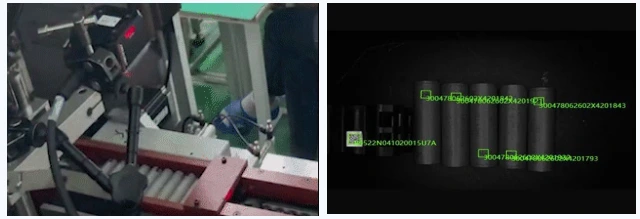
Installation and reading view from the same cylindrical-cell application.
Select an image to view it at full size.
Read a rotating cell within a usable angular window
Swipe across the table to compare all columns →
| Condition | Approach to evaluate | Selection check |
|---|---|---|
| Code fully visible in one orientation | Evaluate triggered frame sequences during rotation. | Measure the usable angle and exposure. |
| Curved or distorted code | Evaluate decoder tolerance on actual marks. | Do not assume a planar-code test transfers. |
| Repeated reads during rotation | Deduplicate within the current cell event. | Reset reliably when the cell changes. |
Balance visible code width, motion and illumination
Map the angular range in which the entire symbol and necessary surrounding area remain observable. Near the edge of that window, curvature and foreshortening can compress code detail. Rotation speed and exposure determine motion blur; increasing exposure to overcome a dark mark may destroy module separation.
Compare lighting arrangements at the moving surface rather than choosing one from a stationary image. If the usable window is too narrow, controlled rotation, another viewing direction or a revised station geometry may help. A faster decoder cannot replace missing sharp frames. The trigger and cell-handling sequence must also establish which rotation belongs to which cell.
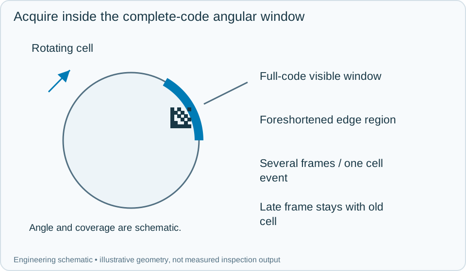
On a small screen, scroll across the diagram to inspect the labels.
Worked example: the code appears in several consecutive frames
In an illustrative cycle, the fixture creates cell event A and starts rotation. Early frames do not show the complete symbol. Later frames produce the same valid identity several times. Merge them under A and issue one accepted read only after content and binding requirements are satisfied.
If the required scan window ends without an accepted code, hold A for the agreed recovery route; distinguish no visible symbol from a visible but undecodable symbol using the stored images. When A leaves and B arrives, close A's acquisition window. A delayed decode from A must not populate B's identity field. If two different codes are observed under one cell event, investigate event boundaries or coverage instead of accepting the first result automatically.
Swipe across the table to compare all columns →
| Observed evidence | Inspection decision | Action and retained record |
|---|---|---|
| Several sharp frames decode the same symbol during one cell's rotation. | One cell identity with repeated observations. | Merge under the active cell event, validate the content and binding, then issue one final read and handling result. |
| The complete symbol never enters the qualified angular window. | Coverage failure rather than a proven decoder limitation. | Retain the rotation sequence, hold the cell and adjust presentation or view geometry before evaluating further decoding settings. |
| A valid result arrives after the next cell has entered the fixture. | Late response belongs to the previous cell. | Preserve its original acquisition event and block it from populating the new identity field; reconcile held cells through the defined recovery route. |
Validate the window and the cell handoff
Test marks at different starting angles, permitted rotation variation, reflective finishes, incomplete symbols and delayed decoder messages. Retain the cell event, acquisition sequence, selected image and final handling confirmation. A successful retry belongs to the held cell only while its physical identity remains established.
Compare dedicated readers with camera systems according to angular coverage, exposure control and interface behaviour. Separate identity reading from visible DPM-quality inspection and from cell electrical tests; each may require different evidence and acceptance rules.
Swipe across the table to compare all columns →
| Challenge | What to verify |
|---|---|
| Lowest normal mark contrast | Measure no-reads at required rotation. |
| Code near a wrap seam | Check complete module visibility. |
| Repeated valid frames | Output one identity for the cell. |
| No code or stalled roller | Stop retries after a defined limit and report the fault. |
Cell marks, rotation and trigger data to provide
Provide cell diameter, mark placement, rotation range, surface finishes and the loading/trigger sequence.
Use the barcode verification grading guide to develop the next step.
Define the wider inspection responsibility in dpm code reading.
Translate these view and interface requirements into equipment choices with code reader selection.
Use the optical and recovery challenges above when applying the architecture choices in vision-system comparison guide.
Scope and budget
The vision system cost guide helps compare optical coverage, cell handling and the trigger logic for a rotating surface.
Testing and handover
Use the testing and handover process to challenge different mark angles and ensure a late result cannot be assigned to the next cell.