Application guide by addaScanCompare the inspection task, imaging conditions and validation steps with your own production line.
- Inspection task
- Silicon ingot end-face DPM reading
- Decision focus
- silicon ingot end-face dpm reading
- Station planning
- Check visibility before attempting identity recovery
- Illustrative scenario
- the code disappears after processing
Present the silicon ingot’s marked end face
The application images show the physical product and imaging conditions. The engineering diagram below explains the inspection logic and recovery decisions.
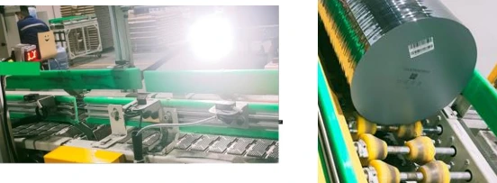
The original installation detail shows the rod end-face presentation.

Selected marked region of the silicon rod; inspection content is unchanged.
Select an image to view it at full size.
Read the ingot identity across surface and pose changes
Swipe across the table to compare all columns →
| Condition | Approach to evaluate | Selection check |
|---|---|---|
| Fresh clear DPM | Use as an optical baseline. | It is not the worst production condition. |
| Reflective or contaminated face | Compare lighting angles and exposure on process samples. | Separate glare from missing mark information. |
| Large pose/depth variation | Evaluate field of view, focus and handling together. | Test extremes rather than one central rod. |
Check visibility before attempting identity recovery
Map the nearest and farthest end-face positions and permitted tilt. Verify module detail at the worst combination of field position, focus and reflection. If only one portion of the code is soft while neighbouring surface detail is also blurred, investigate pose and focus. A local deposit over otherwise sharp detail points towards contamination instead.
Compare lighting directions to control reflections from the end face. More exposure cannot restore a covered or physically damaged module. A dedicated DPM reader may suit a stable presentation; external optics or another camera arrangement can be justified by the required pose envelope. Any cleaning step must follow the material process, not an improvised vision-station procedure.
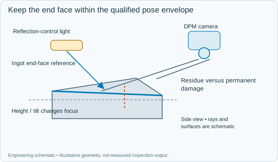
On a small screen, scroll across the diagram to inspect the labels.
Worked example: the code disappears after processing
In an illustrative sequence, an ingot's mark is readable before processing but partly obscured afterwards. Confirm the ingot event and inspect the full end-face image. If an approved cleaning step removes the deposit, reread the same identified ingot and retain both images. Recovery supports a contamination diagnosis.
If missing or altered modules remain in clear views, treat the mark as damaged or unresolved. Hold the ingot for authorised identity reconciliation. Do not assign a remembered previous code solely because it is plausible, and do not create a replacement mark without the required identity controls. A late successful result from another ingot cannot resolve this event. Once identity is re-established through the approved process, record the evidence, any authorised remarking reference and the final handling decision.
Swipe across the table to compare all columns →
| Observed evidence | Inspection decision | Action and retained record |
|---|---|---|
| Approved cleaning restores modules previously covered by residue on the same ingot. | Recoverable contamination supported by before-and-after evidence. | Keep both images, manufacturing stage and ingot event, validate the recovered identity and record the final authorised disposition. |
| Clear qualified views still show physically missing or altered mark modules. | Permanent damage or unresolved identity. | Hold the ingot for controlled reconciliation; do not assign a remembered code or create a replacement mark without the required authorisation record. |
| Module detail degrades at an allowed height or tilt extreme while the centre pose reads. | The optical pose envelope is not yet qualified. | Retain pose and crops, revise optics or presentation and repeat the full allowed geometry and surface-condition trial before acceptance. |
Validate the full process envelope
Include approved surface finishes, residues, permanent mark damage, height extremes and tilted faces. Test both pre-process and post-process conditions where the station must operate. Retain full images, code crops, manufacturing stage, cleaning or reread attempts and binding outcomes.
A successful decode establishes a candidate identity, not material purity or end-face dimensional quality. If those requirements share the station, specify separate checks and acceptance evidence. Keep unavailable imaging distinct from a confirmed wrong identity so recovery follows the right path.
Swipe across the table to compare all columns →
| Challenge | What to verify |
|---|---|
| Marks after each relevant process stage | Identify where readability deteriorates. |
| Different rod positions | Check complete code coverage and focus. |
| Contaminated or damaged mark | Define cleaning, retry and hold rules. |
| Unexpected valid identity | Apply the manufacturing-record check. |
Ingot marks and surface finishes to compare
Provide processed rods or representative end-face samples, mark geometry, contamination states and handling tolerances.
Use the barcode verification grading guide to develop the next step.
Define the wider inspection responsibility in dpm code reading.
Translate these view and interface requirements into equipment choices with code reader selection.
Use the optical and recovery challenges above when applying the architecture choices in vision-system comparison guide.
Scope and budget
Use the vision system cost guide to compare views, surface preparation assumptions and the code-data handover for ingot faces.
Testing and handover
The testing and handover process should include contamination, finish variation and the handling of uncertain marks at the permitted positions.