Application guide by addaScanCompare the inspection task, imaging conditions and validation steps with your own production line.
- Inspection task
- Full-tray PCB code reading
- Decision focus
- full-tray pcb code reading
- Station planning
- Compare centre and corner evidence at original resolution
- Illustrative scenario
- the read count is right but one location is wrong
Small PCB codes across the full tray field of view
The application images show the physical product and imaging conditions. The engineering diagram below explains the inspection logic and recovery decisions.
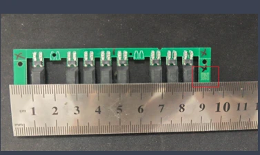
The sample and ruler show the small marks and the tray-reading problem.
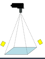
Original schematic of camera and external light geometry; source text captions are replaced by this English caption.
Select an image to view it at full size.
Test the smallest PCB code at the tray's worst position
Swipe across the table to compare all columns →
| Condition | Approach to evaluate | Selection check |
|---|---|---|
| Single wide view | Evaluate resolution and illumination across the entire tray. | Challenge the smallest corner code. |
| Multiple cameras | Compare coverage and result association. | Additional views require a reliable common tray identity. |
| Sequential reading | Compare handling time and pose repeatability. | A smaller field of view can improve code detail. |
Compare centre and corner evidence at original resolution
Estimate module sampling from usable pixels across the field, physical code size and symbol modules, then verify it on actual marks. Lens distortion, board tilt and corner focus can make the real result worse than the central estimate. Inspect full-resolution code crops from the centre and extreme tray positions.
Printed and through-hole symbols may require different illumination. Reflected light that reveals printed contrast can obscure a hole pattern, while backlighting needs an unobstructed path through the board and fixture. One lighting arrangement may cover both only after sample testing. If full-tray coverage sacrifices required detail, compare multiple views or an indexed acquisition with an explicit tray-coordinate merge.
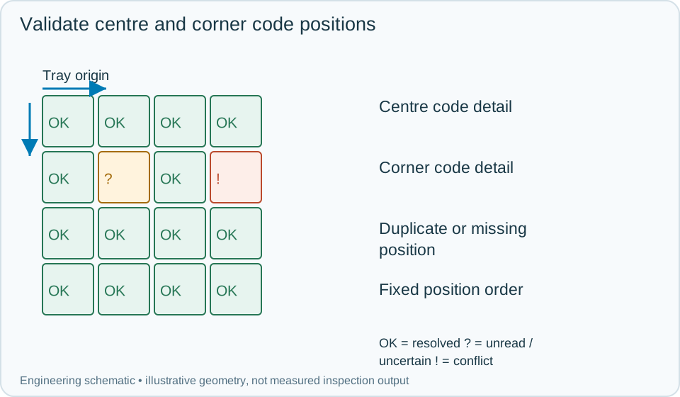
On a small screen, scroll across the diagram to inspect the labels.
Worked example: the read count is right but one location is wrong
In an illustrative tray, every expected number of strings is returned, but a symbol from a neighbouring board occupies the region of an unread corner position. Locate each candidate in tray coordinates and enforce the expected position map. The tray remains incomplete until that corner position supplies its own accepted code.
A repeated identity at two valid positions is another conflict even when the count matches. Hold the tray for identity reconciliation rather than silently removing duplicate strings. For a controlled reread, retain the tray event and orientation, resolve only the missing or conflicting positions and verify uniqueness again. Clear the accumulated set when the tray changes. Store code locations, image crops, unresolved reasons and the final physical tray action so the result can be reconstructed.
Swipe across the table to compare all columns →
| Observed evidence | Inspection decision | Action and retained record |
|---|---|---|
| The centre code is sharp while the smallest corner code loses module detail. | Full-tray optical coverage is not established. | Keep original-resolution crops and pose conditions, revise optics or view layout and repeat corner and centre trials together. |
| The returned string count matches but one position is missing and another identity is duplicated. | Tray set is incomplete or conflicting. | Store position assignments and candidate images, hold the tray and reconcile missing and duplicate locations under its active event. |
| Printed codes read but support geometry blocks the illumination required by hole codes. | One marking type lacks usable evidence. | Record code type and view validity, restore the optical path or add the qualified view before completing the tray result. |
Validate the complete set under loading variation
Challenge tray rotation, edge positions, mixed symbol types, repeated codes and differing board heights. Check that output order follows an explicit position convention rather than the decoder's incidental discovery order.
A dedicated multi-code reader may be suitable when its optical coverage and position outputs meet the requirement. A more flexible camera system becomes useful for complex association or additional board checks, but still needs the same corner-detail and complete-set tests. Reading a symbol is distinct from grading its print quality.
Swipe across the table to compare all columns →
| Challenge | What to verify |
|---|---|
| Every occupied tray position | Confirm identity and position mapping. |
| Printed and through-hole marks | Evaluate separately under the selected lighting. |
| Missing or duplicate code | Fail completeness even when other codes read. |
| Tray shifted or tilted | Keep all required modules inside the usable image. |
PCB trays and code layouts for a reading trial
Provide the complete tray, smallest codes of each process, permitted pose variation and the required output order.
Use the hikrobot vs keyence guide to develop the next step.
Define the wider inspection responsibility in dpm code reading.
Translate these view and interface requirements into equipment choices with code reader selection.
Use the optical and recovery challenges above when applying the architecture choices in vision-system comparison guide.
Scope and budget
Use the vision system cost guide to compare code detail across the full field, tray presentation and ordered-data output.
Testing and handover
Include one unreadable position, a duplicate value and a new tray during a retry in the testing and handover process.