Application guide by addaScanCompare the inspection task, imaging conditions and validation steps with your own production line.
- Inspection task
- Through-hole PCB code reading
- Decision focus
- through-hole pcb code reading
- Station planning
- Diagnose obstruction, blur and blocked holes separately
- Illustrative scenario
- a code reads on the bench but fails in the conveyor
Lighting trials for through-hole codes on dark PCB
The application images show the physical product and imaging conditions. The engineering diagram below explains the inspection logic and recovery decisions.
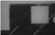
Application image from the initial lighting comparison.
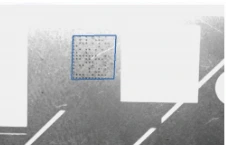
Second selected lighting-comparison image; the text describes the further backlighting arrangement.
Select an image to view it at full size.
Keep the light path clear through the PCB hole code
Swipe across the table to compare all columns →
| Condition | Approach to evaluate | Selection check |
|---|---|---|
| Ordinary front illumination | Use as a baseline image. | Look for washed-out or low-contrast hole patterns. |
| Angled front light | Evaluate reflection reduction. | Check whether all modules become distinguishable. |
| Added backlight | Evaluate transmission through the code holes. | Verify fixture clearance and moving-line exposure. |
Diagnose obstruction, blur and blocked holes separately
Draw the camera, PCB, support and backlight in cross-section. Check the full allowed board position range against the support geometry. If a rail masks part of the code, change the inspection point or support arrangement. Confirm that the revised support still handles the board safely and repeatably.
Then test exposure against motion. Directional smearing of many hole edges suggests blur; a local filled-looking module may indicate a blocked hole or physical obstruction. More light can permit a shorter exposure, but must be evaluated for contrast and glare from adjacent structures. Use original-resolution crops to compare these effects instead of treating every no-read as the same tuning problem.
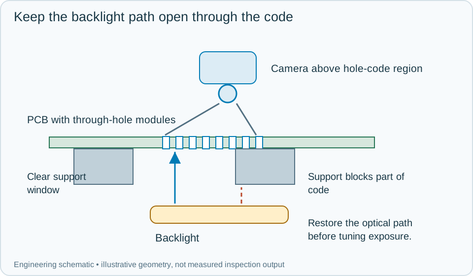
On a small screen, scroll across the diagram to inspect the labels.
Worked example: a code reads on the bench but fails in the conveyor
In an illustrative setup, a stationary board over an open backlight produces a clear code. In the machine, the same section is dark because a support passes beneath it. Record an unusable-image result and correct the optical path. Lengthening exposure does not remove a solid obstruction.
After moving to a clear window, the code becomes visible but elongated at line speed. Adjust the lighting and exposure, then verify sharp modules during motion. If a particular hole remains blocked across sharp images, route the board to the agreed inspection or cleaning process and reread the same identified item. Finally validate the decoded identity against the production requirement. Store distinct no-image, unusable-image, no-decode and wrong-identity outcomes, and prevent any of them from inheriting the previous board's successful code.
Swipe across the table to compare all columns →
| Observed evidence | Inspection decision | Action and retained record |
|---|---|---|
| The same hole-code segment is dark wherever a conveyor support passes beneath it. | Physical light-path obstruction. | Retain the machine cross-section and image evidence, change support or inspection position and validate the entire allowed board placement range. |
| Many hole edges smear in the motion direction but become sharp when the board stops. | Exposure-motion mismatch. | Compare moving crops after lighting and exposure adjustment. Keep the qualified line condition with the recipe rather than relying on stationary reads. |
| A sharp complete image decodes but the returned board identity is not expected. | Content or association failure rather than optical no-read. | Hold the board, preserve the string and event, and reconcile the production requirement without reusing the previous board's value. |
Challenge the physical presentation, not only the code samples
Test lateral drift over supports, board warp, start-stop motion, hole contamination and normal code-manufacturing variation. Confirm that the inspection event still matches the board at the release point after a stop.
A reader may be sufficient for identity if the holes are consistently visible. Additional camera logic is justified when board location, obstruction detection or other inspection features form part of the task. Code readability alone does not establish dimensional quality of every manufactured hole.
Swipe across the table to compare all columns →
| Challenge | What to verify |
|---|---|
| Dark and reflective board variants | Check the contrast of individual modules. |
| Board over the actual conveyor | Confirm the backlight path is not blocked. |
| Motion at the required trigger point | Measure no-reads under production exposure. |
| Damaged or partially blocked code | Define the retry and hold policy. |
PCB finishes and through-hole marks to test
Provide physical boards, marking geometry, transport details, access underneath the code and expected data format.
Use the barcode verification grading guide to develop the next step.
Define the wider inspection responsibility in dpm code reading.
Develop the related acceptance requirements with machine vision lighting.
Use the optical and recovery challenges above when applying the architecture choices in vision-system comparison guide.
Scope and budget
The vision system cost guide helps scope optical access, board guidance and the code-data interface for through-hole marks.
Testing and handover
Use the testing and handover process to test dark material variation and the action taken when the mark cannot be decoded.