Application guide by addaScanCompare the inspection task, imaging conditions and validation steps with your own production line.
- Inspection task
- Small wafer Data Matrix reading
- Decision focus
- small wafer data matrix reading
- Station planning
- Calculate the sampling relationship, then verify the image
- Illustrative scenario
- both redundant codes read but disagree
Locate a small Data Matrix mark on the wafer
The application images show the physical product and imaging conditions. The engineering diagram below explains the inspection logic and recovery decisions.
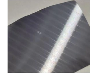
Original wafer sample bearing the small mark; source software menus are not shown.
Select an image to view it at full size.
Preserve small Data Matrix detail across the wafer view
Swipe across the table to compare all columns →
| Condition | Approach to evaluate | Selection check |
|---|---|---|
| Largest possible view | Check pixels per module at the smallest code. | A wider view reduces detail at fixed sensor resolution. |
| Restricted working distance | Compare compact optics with required focus range. | Validate actual mounting clearance. |
| Two redundant marks | Define acceptance and conflict rules. | Do not silently choose one of two inconsistent identities. |
Calculate the sampling relationship, then verify the image
For a fixed sensor, increasing the physical field width reduces the pixels available per code module. The code's module count matters as well as its printed or marked size. Use that relationship to screen optical arrangements, then examine actual centre and corner images under the allowed height and angle variation. A nominal calculation is not a guaranteed decoder limit.
If redundant codes carry the same intended identity, define whether either may provide a candidate and when both must agree. Redundancy can improve availability but creates a conflict case that must be handled. A larger view or additional exposure is useful only if it preserves module detail and associates both symbols with the same wafer event.
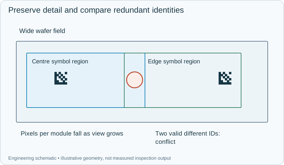
On a small screen, scroll across the diagram to inspect the labels.
Worked example: both redundant codes read but disagree
In an illustrative wafer inspection, the central symbol decodes and the edge symbol does not. If the qualified process permits one valid redundant identity, validate that candidate against the expected record and log which symbol supplied it. If both are required, hold for a controlled reread.
On another wafer, both symbols decode to different identities. Do not select the more confident string or combine pieces of the values. Record an identity conflict, hold the wafer and inspect the marking and event association. A reread must remain tied to that wafer. When a focus adjustment restores the edge symbol, repeat centre and edge validation over the full permitted envelope before accepting the new setup. Preserve full images and module crops so optical improvement is distinguishable from a changed business rule.
Swipe across the table to compare all columns →
| Observed evidence | Inspection decision | Action and retained record |
|---|---|---|
| The centre symbol is resolved while the edge symbol lacks module detail. | Optical envelope or sampling needs qualification. | Keep original-resolution crops and wafer pose, adjust the view arrangement and validate centre and edge together before changing the accepted recipe. |
| Both redundant symbols decode to different valid-format identities. | Identity conflict, not a choice between confidence scores. | Hold the wafer, preserve both symbol locations and strings and use the authorised reconciliation process before binding or release. |
| Only one redundant mark reads and the approved process permits a single valid identity. | Conditional candidate subject to content and association checks. | Record which mark supplied the identity, retain the missing-mark reason and apply the agreed validation without silently weakening a two-mark requirement. |
Compare optics and interfaces together
Challenge smallest symbols, field corners, height extremes, low contrast, missing redundant marks and conflicting marks. Verify that the station clears its candidate values between wafers and records which code position was used.
A dedicated reader can be suitable for stable identity acquisition; additional imaging control may be needed for constrained optics or appearance inspection. Neither a decode nor agreement between redundant codes establishes mark-quality grading unless a qualified verification process is separately applied.
Swipe across the table to compare all columns →
| Challenge | What to verify |
|---|---|
| Smallest and weakest marks | Measure read success and incorrect decodes separately. |
| Oxidised surface variation | Check contrast under the selected illumination. |
| Wafer at view edges | Verify focus and usable resolution. |
| Two differing code values | Confirm the conflict response. |
Wafer codes and permitted lighting to test
Provide physical marked wafers, module count, surface stages, height range and installation-space drawings.
Use the barcode verification grading guide to develop the next step.
Translate these view and interface requirements into equipment choices with code reader selection.
Define the wider inspection responsibility in dpm code reading.
Use the optical and recovery challenges above when applying the architecture choices in vision-system comparison guide.
Scope and budget
Use the vision system cost guide to consider optical detail, lighting clearance and handling interfaces for the small wafer marks.
Testing and handover
Include surface-stage changes and a missing or unreadable mark in the testing and handover process.