Application guide by addaScanCompare the inspection task, imaging conditions and validation steps with your own production line.
- Inspection focus
- Physical glass edge relative to the hob frame
- Primary theme
- Dimensional measurement
- Decision evidence
- Offset decorative border
- Trial priority
- Offset print on correct glass
Locate the physical glass and frame datums
The original English schematic explains the observable features and the proposed decision. The tables below set out the conditions to test on your own line.
Swipe across the diagram to see all details →
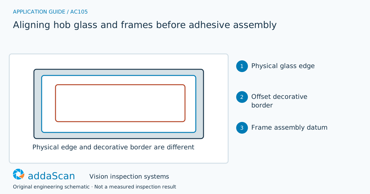
Align the physical glass to the frame datum. A decorative printed border can move independently and should not silently become the assembly reference. Original schematic.
Select an image to view it at full size.
Separate artwork location from assembly geometry
Transparent or reflective glass edges need lighting that makes the actual boundary visible. Locate frame features in the same calibrated coordinate system and calculate the required translation and rotation. Check whether the fixture or adhesive application changes the relationship after the first measurement. Printed graphics can be useful for identity, but their tolerances may differ from the mechanical alignment requirement.
Identify which glass edge, hole, frame feature or locating surface defines the assembly. A decorative border can be offset within its own print tolerance while the glass is physically correct. If the vision system follows the border as a convenient high-contrast feature, it may command a wrong mechanical placement. Record any permitted use of print as an indirect reference and validate its relationship to the physical datum.
Glass tilt, transparent edges and reflected surroundings can shift the apparent boundary. Test the actual glass treatment and frame finish under the intended fixture conditions. Keep the alignment result in the coordinate system used by the handling or adhesive process, with a check that the reference remains valid until the action.
Choose edge or profile evidence for the actual assembly reference
Swipe across the table to compare all columns →
| Approach | Useful when | Limit or integration responsibility |
|---|---|---|
| Artwork alignment | Print-to-frame appearance requirements | Only valid if the specification names the print as datum. |
| Physical-edge alignment | Mechanical glass-to-frame relationship | Needs reliable edge imaging, calibration and post-placement confirmation. |
Edge imaging fits exposed, stable physical boundaries. Complementary geometry or a different presentation may be needed where reflection hides the edge or out-of-plane pose matters. Compare methods using deliberately offset print on correctly dimensioned glass, not only well-centred artwork.
Offset print must not shift correctly positioned glass
Illustrative scenario: the decorative border is displaced while the glass edge is within its allowed geometry. Keep the physical edge as the assembly reference rather than shifting the glass to follow the print.
Recalibrate if the edge location is unreliable, verify the proposed correction on reference samples and measure the actual relationship after placement. Release against the mechanical specification, with any artwork issue recorded separately.
If the glass moves after acquisition, invalidate or update the alignment command under a qualified tracking rule. Verify the relevant relationship before irreversible joining. A successful robot movement acknowledgement does not prove the glass remained at the required datum.
Challenge reflections and movement before bonding
Swipe across the table to compare all columns →
| Challenge sample or event | Expected behaviour to establish | Evidence to retain |
|---|---|---|
| Offset print on correct glass | Do not introduce mechanical error by following the artwork. | Physical glass/frame datums, decorative-border offset, independent alignment reference and the resulting placement decision. |
| Glass tilt and reflective edges | Validate physical edge localisation. | Glass pose and surface reflection, valid edge/profile regions, locating result and unresolved acquisition handling. |
| Movement during adhesive placement | Measure the final relationship again. | Capture and placement events, observed movement, adhesive-process permission and final pre-joining alignment evidence. |
Include correct glass with offset print, tilted presentation and movement after localisation. Review physical alignment and artwork appearance separately. Bond strength or cure requirements need their own acceptance process.
Visible alignment does not prove bond quality
Geometric alignment does not prove adhesive strength, glass integrity or appliance safety.
Define the permitted glass-to-frame relationship
Share permitted photos or drawings, plus details of datum drawings, gap limits, print tolerances, glass finishes and the placement sequence. Agree any physical sample arrangements after the initial assessment.
Dimensional measurement helps define the coordinate relationship and repeatability required for assembly. Glass acquisition and the placement interface must be qualified together.
Keyboard inspection with stitched 3D views combines views for assembly inspection. Common-coordinate discipline is useful here, but the glass and frame require their own physical datums.
Use the cost and scope guide to understand the station boundary. An estimate depends on the required views, product presentation, exception handling and connection to the existing line. A similar camera does not establish the price of this application.
Compare lighting, processing, interfaces and support in the HIKROBOT and other vision solutions guide. Agree sample testing, acceptance responsibilities and handover through the delivery process.