Application guide by addaScanCompare the inspection task, imaging conditions and validation steps with your own production line.
- Inspection focus
- LED state tied to the appliance test step
- Primary theme
- Machine vision defect detection
- Decision evidence
- Reflection still bright
- Trial priority
- External reflection during off step
Match each visible indicator to the active test step
The original English schematic explains the observable features and the proposed decision. The tables below set out the conditions to test on your own line.
Swipe across the diagram to see all details →
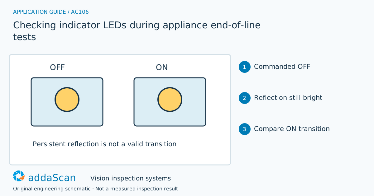
An LED image is meaningful only for its acknowledged test step. Reflection, exposure timing and missing frames must be distinguished from the expected on/off state. Original sequence schematic.
Select an image to view it at full size.
Observe transitions as well as brightness
Locate the indicator regions for the correct appliance variant and control ambient light. Compare off and on observations with enough settling time for the actual electronics and camera exposure. Multiplexed or pulsed indicators can interact with exposure timing, so test for apparent flicker or partial intensity. Keep the test command, acknowledgement and frame timing together.
Define the expected state of each indicator for each commanded test step, including whether colour, position or timing matters. A bright spot in the correct location is not sufficient if the appliance was commanded off. Keep the command, acknowledgement and acquired frame linked so an image from the previous state cannot satisfy the current step.
Exposure and indicator drive can interact. A pulsed LED may appear dim or absent in one short exposure, while ambient reflection may brighten a nominally off region. Qualify acquisition against the actual test sequence and permitted ambient conditions. Do not raise brightness thresholds to conceal a timing problem; establish when a frame represents the intended state.
Compare a bright image with a qualified on/off sequence
Swipe across the table to compare all columns →
| Approach | Useful when | Limit or integration responsibility |
|---|---|---|
| Single bright-frame check | Simple static illuminated feature | Can accept reflection or the wrong test state. |
| Step-linked on/off sequence | Functional visible response | Needs timing, ambient-light control and complete test-step records. |
A static image can check a settled, well-defined visible state. A state sequence needs synchronised acquisition and step-level results. Compare the arrangements using both actual indicator changes and unchanged hardware under varying exposure, rather than evaluating only bright-on examples.
An off-step reflection is not evidence of a working LED
Illustrative scenario: a bright spot persists in an indicator region during the commanded off step. Compare the sequence to distinguish reflection from a valid state transition.
Hold the appliance if the required response is unresolved and rerun the specified steps under controlled conditions. Preserve the first sequence and the retest. Release only after every required state has a valid observation tied to its step.
If acknowledgement or a frame is missing, keep that test step unresolved and repeat it under the agreed sequence. A later bright frame cannot complete an earlier off-state check. Preserve retries against the same appliance test event without skipping required states.
Challenge pulsed light and missing test acknowledgements
Swipe across the table to compare all columns →
| Challenge sample or event | Expected behaviour to establish | Evidence to retain |
|---|---|---|
| External reflection during off step | Do not count it as a successful LED response. | Appliance/test-step ID, off command and acknowledgement, reflected-light image and rejection of the false-on observation. |
| Pulsed indicator and varied exposure | Establish reliable capture timing. | Indicator drive state, exposure/acquisition timing, repeated frames and the qualified interpretation of pulsed light. |
| Missing acknowledgement or frame | Keep the test incomplete until rerun. | Expected step/frame list, missing acknowledgement or image, repeat sequence and complete final optical-state record. |
Test ambient reflections during off states, pulsed indicators and delayed or absent responses. Agree how the test controller prevents a partial optical sequence from being reported as a complete functional test.
Optical LED states are only part of functional testing
Visible indicator response does not establish the full electrical or safety function of the appliance.
Define the test-step and camera-acquisition handshake
Share permitted photos or drawings, plus details of LED positions, colours, test sequences, timing signals and ambient-light conditions. Agree any physical sample arrangements after the initial assessment.
Vision station scope and responsibilities helps define the optical check and the existing test-controller interface. This scope does not imply supply of a complete electrical test bench.
Inspecting printed symbols on automotive controls inspects printed symbols on controls. Static symbol appearance and commanded indicator behaviour require different acquisition and acceptance rules.
Use the cost and scope guide to understand the station boundary. Optical state acquisition and the interface to the existing test sequence require a specific scope; this is not a complete electrical test-bench offer.
Compare lighting, processing, interfaces and support in the HIKROBOT and other vision solutions guide. Agree sample testing, acceptance responsibilities and handover through the delivery process.