Application guide by addaScanCompare the inspection task, imaging conditions and validation steps with your own production line.
- Inspection focus
- Retaining hook relative to the gear slot
- Primary theme
- Assembly verification
- Decision evidence
- Hook beside groove
- Trial priority
- Hook beside slot
Locate the hook end relative to its intended slot
Reference imagery and an original English schematic explain the observable features and the proposed decision. The tables below set out the conditions to test on your own line.
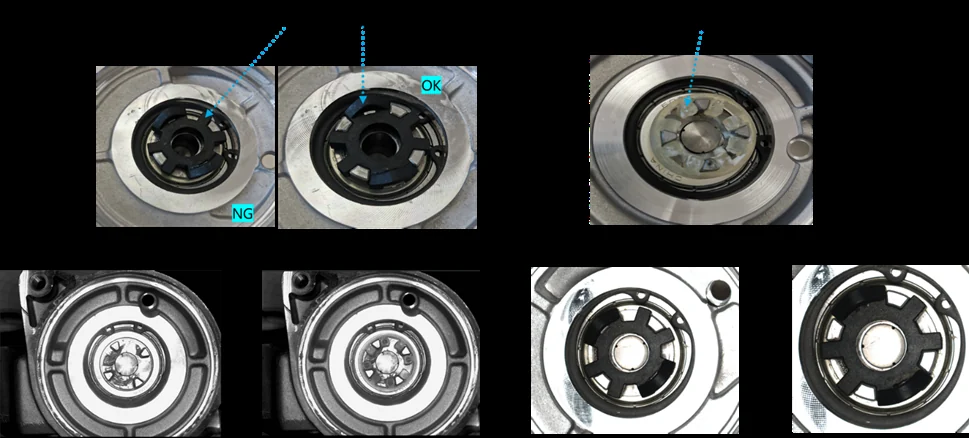
The views illustrate how small assembly features are isolated within the component. The acceptance workflow below must be defined for the actual gear.
Swipe across the diagram to see all details →
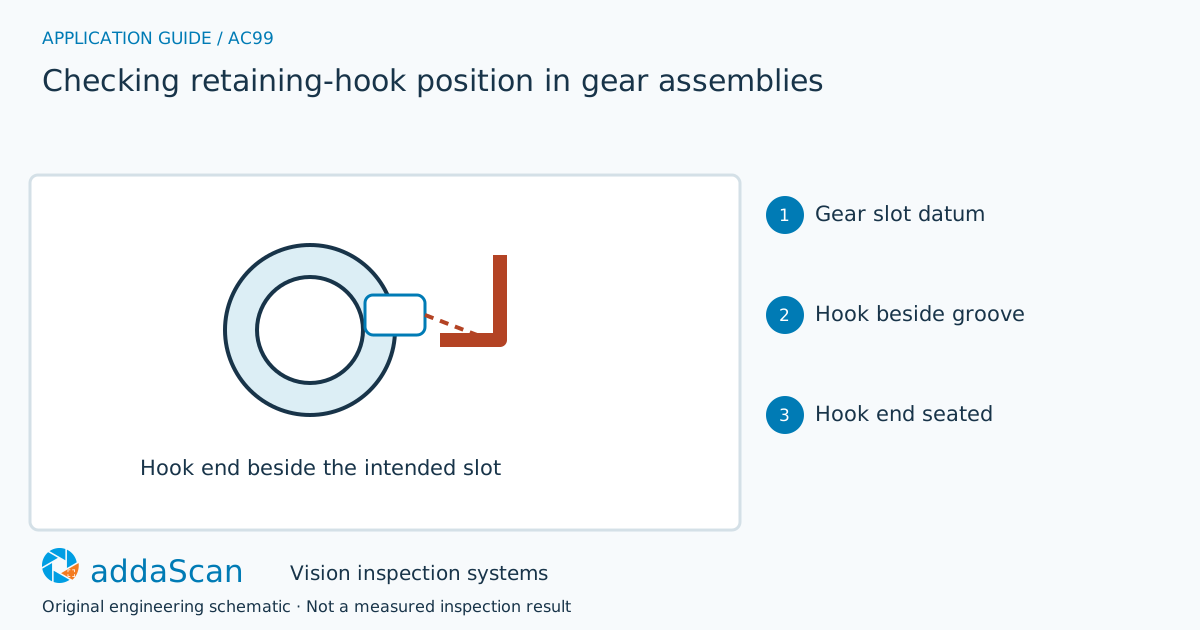
The retaining hook must meet the specified slot relationship. A detected hook beside the slot remains an assembly failure. Original schematic; retention force is not measured.
Select an image to view it at full size.
Choose the feature that demonstrates visible engagement
An overall object detector may find the hook regardless of installation position. Define the visible relationship that separates correctly located, partially seated and displaced hooks. Gear rotation must be normalised before using positional limits. Metallic reflections, grease and neighbouring teeth can hide the endpoint, so test illumination and viewing access with assembled parts rather than loose components alone.
Define the physical feature that distinguishes engagement from proximity. A visible hook body or endpoint can lie beside the slot while giving a convincing component-presence result. Locate the gear or carrier datum and evaluate the endpoint against the approved slot relationship, including the visible depth or shoulder evidence required by the assembly definition.
Reflective edges can move with lighting and gear rotation. Use qualified part-relative regions rather than fixed screen coordinates. If the decisive contact is hidden, limit the claim to the visible feature or specify an additional observation; do not infer a hidden lock from the presence of the hook.
Choose views of the engagement feature rather than the part outline
Swipe across the table to compare all columns →
| Approach | Useful when | Limit or integration responsibility |
|---|---|---|
| Hook presence | Missing-component detection | Can pass a displaced hook. |
| Gear-relative endpoint check | Visible location and seating relationship | Needs a repeatable datum and access to the engagement region. |
A single view can work where the endpoint and receiving feature are exposed together. Complementary views or profile evidence may be needed where overlap hides the relationship. Compare their actual engagement coverage and locating stability, not simply whether they find the hook.
A hook beside the slot must not count as fitted
Illustrative scenario: the hook appears in the image but its end lies beside the groove. Hold the assembly and retain the registered region.
After rework, relocate the gear and inspect the endpoint again; do not compare the new image against stale coordinates. Release follows a valid engagement-geometry result, while an obscured endpoint requires re-presentation or the agreed manual route.
After reseating the hook, inspect the joint again with the part located from its datum. Preserve the original failure and any independent mechanical check. An operator placing the hook near the correct location does not close the engagement requirement.
Challenge rotation, glare and reworked assemblies
Swipe across the table to compare all columns →
| Challenge sample or event | Expected behaviour to establish | Evidence to retain |
|---|---|---|
| Hook beside slot | Fail location despite presence. | Gear/slot datum, hook endpoint region, adjacent-but-unengaged sample and the explicit engagement decision. |
| Rotated gear and reflective endpoint | Maintain registration or return unknown. | Gear rotation, reflective endpoint images, locating result and the evidence distinguishing glare from the hook feature. |
| Reworked assembly | Save before/after evidence under the same part event. | Original engagement fault, rework sequence, newly located joint and the result authorising release. |
Include an adjacent hook, partial engagement and accepted joints across the allowed part orientation. Agree how an unseen locking feature is handled. Retention force and hidden deformation need independent evidence.
Visible engagement does not prove retention force
Visible seating does not establish retaining force or functional engagement under load.
Prepare the gear datum and approved hook states
Share permitted photos or drawings, plus details of gear and hook variants, seated and displaced sample examples, grease conditions and assembly access. Agree any physical sample arrangements after the initial assessment.
Assembly verification and error proofing defines visible assembly verification. The hook’s decisive engagement feature and required view coverage determine whether a simple presence camera is sufficient.
Kit packing: count, orientation and identity checks component identity and placement in kits. For a retaining hook, placement must additionally establish the specified visible engagement.
Review the indicative station budget and exclusions. The assembly budget is relevant to visible hook engagement; hidden locking geometry or 3D measurement may require additional equipment.
Compare lighting, processing, interfaces and support in the HIKROBOT and other vision solutions guide. Agree sample testing, acceptance responsibilities and handover through the delivery process.