Application guide by addaScanCompare the inspection task, imaging conditions and validation steps with your own production line.
- Inspection focus
- Image stretch during web acceleration
- Primary theme
- Web inspection
- Decision evidence
- Startup image stretched
- Trial priority
- Steady speed and acceleration
Relate acquired image rows to actual web movement
The original English schematic explains the observable features and the proposed decision. The tables below set out the conditions to test on your own line.
Swipe across the diagram to see all details →
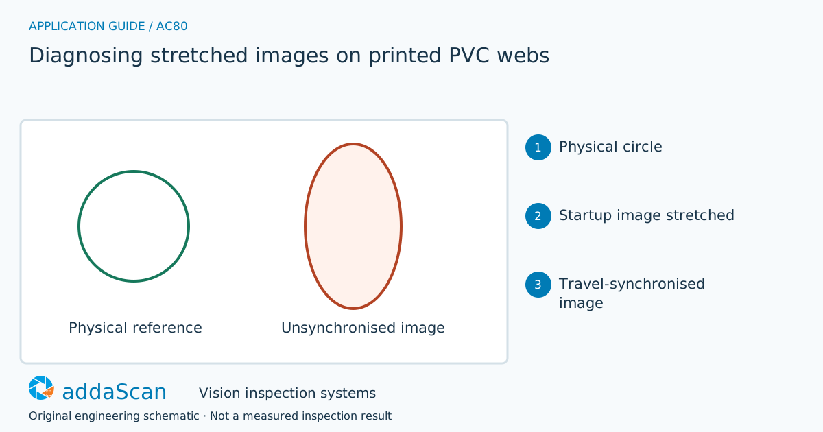
Image length depends on the material distance represented by each acquired row. Compare startup and steady running before treating stretched artwork as a print defect. Original acquisition schematic.
Select an image to view it at full size.
Check the image aspect ratio against physical travel
Line-scan images are assembled from successive lines. If acquisition timing does not follow web movement, speed changes alter the machine-direction scale. Compare encoder mounting, slip, pulses per travel and camera trigger configuration. Cross-web optics may remain correct while the travel direction is distorted. A physical reference mark of known geometry helps separate an imaging fault from actual material elongation.
Record the acquisition mode before adjusting inspection thresholds. With fixed-time line acquisition, a changing material speed changes the distance represented by each image row. Encoder-triggered acquisition can maintain a displacement relationship, but only if pulses represent actual web travel and the camera accepts the required trigger sequence. A drive command is not always evidence of material displacement at the imaging point.
Compare a stable printed feature with an independent material reference through startup and steady running. Look for direction and timing: distortion that follows acceleration or slip points to acquisition or transport, while a physical print-repeat error remains on the material when independently inspected. Exposure and lighting should also be checked for motion blur rather than confusing blur with stretched geometry.
Separate acquisition faults from print-process changes
Swipe across the table to compare all columns →
| Approach | Useful when | Limit or integration responsibility |
|---|---|---|
| Time-based line acquisition | Nearly constant validated speed | Startup can change the scale of the assembled image. |
| Displacement-triggered acquisition | Variable web speed | Requires a reliable encoder reference and camera timing compatibility. |
Evaluate time-based and encoder-related acquisition against the line’s speed range and available position signal. The task is to establish a valid image scale, not to choose the mode with the most attractive nominal resolution. Trigger rate, missed acquisitions and encoder coupling belong in the diagnostic record.
Startup stretch can originate in image sampling
Illustrative scenario: a circular printed feature appears elliptical during acceleration but returns to its usual shape at steady speed. Hold the affected interval and compare its image scale with independently checked material travel.
Correct the synchronisation fault and reacquire representative startup sequences. Release the held material only after reinspection or the agreed disposition. Raising the shape tolerance until the alarm disappears would hide the evidence without resolving its cause.
After changing sampling or encoder coupling, repeat the startup challenge and compare the same reference features. Requalify print inspection using the corrected acquisition; thresholds tuned to distorted images should not be carried forward without review.
Challenge slip, lost triggers and corrected restarts
Swipe across the table to compare all columns →
| Challenge sample or event | Expected behaviour to establish | Evidence to retain |
|---|---|---|
| Steady speed and acceleration | Record reference-shape dimensions and encoder settings. | Actual displacement reference, image feature scale, line-acquisition mode and matched startup/steady-speed records. |
| Controlled slip or trigger loss | Expose invalid image geometry rather than a print decision. | Slip or trigger-loss condition, encoder/camera records, affected image rows and diagnosis separating blur from scale error. |
| Restart after correction | Recheck startup material and retained defect samples. | Correction version, repeated startup sequence, reference geometry and revalidated print-inspection settings. |
Introduce only controlled, agreed diagnostic changes and retain their configuration. Compare images with the physical printed repeat after stopping the web. This avoids accepting an acquisition fix that merely makes one selected image look normal.
A corrected image scale does not validate the print itself
A synchronised image still needs calibrated optics and product tolerances. Genuine film stretch can coexist with acquisition errors.
Prepare encoder, exposure and line-speed records
Share permitted photos or drawings, plus details of startup images, an image of the physical print, encoder location, trigger settings and the speed profile. Agree any physical sample arrangements after the initial assessment.
Web and line-scan inspection provides the line-scan acquisition context. Diagnostic scope must include the web displacement signal, camera triggering and downstream inspection settings.
Roll-label print and registration inspection addresses print defects and registration once the image represents the material correctly. Acquisition distortion must be resolved before interpreting those measurements.
Use the cost and scope guide to understand the station boundary. Line-scan acquisition and encoder or drive-interface changes need a specific diagnostic and integration scope.
For line conditions around image stretch during web acceleration, see plastics and packaging inspection.
Compare lighting, processing, interfaces and support in the HIKROBOT and other vision solutions guide. Agree sample testing, acceptance responsibilities and handover through the delivery process.