Application guide by addaScanCompare the inspection task, imaging conditions and validation steps with your own production line.
- Inspection focus
- A usable physical edge on stacked timber
- Primary theme
- Dimensional measurement
- Decision evidence
- Physical top-board edge
- Trial priority
- Dark grain parallel to the boundary
Find the intended top-board boundary rather than a dark line
The original English schematic explains the observable features and the proposed decision. The tables below set out the conditions to test on your own line.
Swipe across the diagram to see all details →
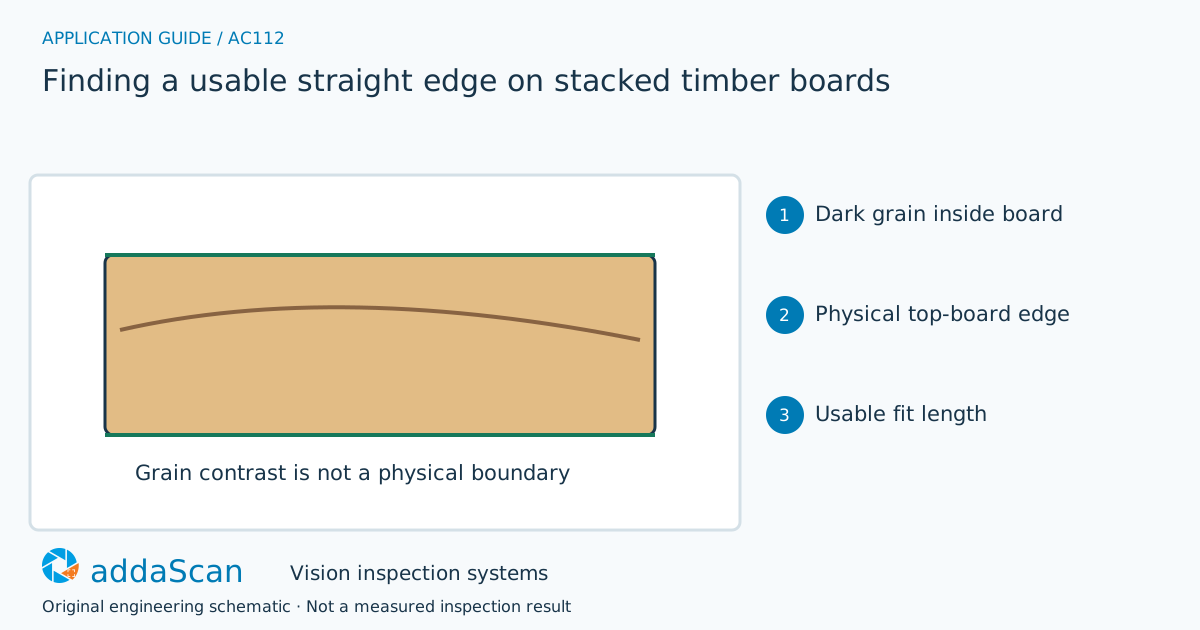
The required line is a physical boundary on the intended top board. Grain or an exposed lower-board edge can be strong image features without being the correct handling reference. Original schematic.
Select an image to view it at full size.
Segment the top board before fitting a line
Warp, bark, knots and staggered boards create several candidate edges. A line fit over all detected contrast can follow grain or a lower board. First establish the top-layer target, then select edge points with supporting geometric evidence. Define minimum usable length and acceptable departure from straightness according to the downstream operation, rather than accepting every mathematically fitted line.
Identify the target board and the physical boundary required by the cutter or handling operation. Dark grain can form a strong line inside the face, while a staggered lower board can expose a convincing edge at the wrong layer. Edge selection therefore needs object and layer context rather than simply the strongest straight feature.
Define the usable edge length and allowed departure from straightness for the intended reference. A short visible segment can produce a fitted line but provide poor evidence for a distant cutting or gripping point. Keep the observed segment separate from any extrapolation, and record occlusion or warp that makes the requested reference uncertain.
Choose appearance or depth evidence for the required edge
Swipe across the table to compare all columns →
| Approach | Useful when | Limit or integration responsibility |
|---|---|---|
| 2D contrast edge | Clear physical boundary with stable presentation | Can follow grain or shadow. |
| Depth-supported edge | Stacked or visually ambiguous boards | Needs top-layer segmentation and sufficient valid edge length. |
Intensity imaging can locate an exposed boundary when it remains distinct from grain and background. Depth may help separate board layers or an edge from a surface mark, but needs valid coverage on the actual timber and stack. Compare methods on the required reference length, not just whether a line can be drawn on one image.
A parallel grain line must not become the handling reference
Illustrative scenario: a dark grain streak forms a strong image edge but the depth surface remains continuous across it. Exclude it as a physical boundary.
Re-segment the top board and fit only supported edge points. If too little edge is visible, re-present or manually arrange the stack through the agreed process. Release coordinates only when the target layer and usable edge satisfy the application limits.
If the stack shifts after acquisition, reidentify the top board and its edge before sending a new reference. A previously fitted line should not survive a changed layer or moved board. Use a controlled alternative where the minimum usable boundary remains hidden.
Challenge staggered boards and short visible edges
Swipe across the table to compare all columns →
| Challenge sample or event | Expected behaviour to establish | Evidence to retain |
|---|---|---|
| Dark grain parallel to the boundary | Do not use it as the physical datum. | Top-board identity, dark internal grain line, observed physical boundary and the rejected false-edge candidate. |
| Staggered lower boards and warped top board | Retain target-layer and fitting evidence. | Stack/layer arrangement, lower-board edges, top-board warp and the evidence assigning the chosen boundary to the intended board. |
| Short or occluded edge | Withhold coordinates until sufficient support is visible. | Observed segment length, occluded portion, fit/extrapolation distinction and the hold or reacquisition decision. |
Include strong parallel grain, staggered layers and deliberately shortened visibility. Compare the resulting reference with an independently located physical edge. Material grading, internal defects and final dimensional acceptance require additional checks.
Edge localisation does not establish timber grade
An edge reference does not grade timber strength, moisture or internal defects.
Define which board and edge the downstream action needs
Share permitted photos or drawings, plus details of board sizes, warp and bark variation, stack patterns and the downstream edge requirements. Agree any physical sample arrangements after the initial assessment.
Dimensional measurement helps define a geometric reference and its repeatability. Board handling, cutting interfaces and any depth acquisition need a specific scope.
Scratch detection on aluminium extrusions examines surface marks on extrusions. This timber task instead needs proof of a physical boundary and layer, so a strong surface line is insufficient.
Use the cost and scope guide to understand the station boundary. Board-edge localisation, any depth sensing and the cutter or robot interface require a separate handling and vision scope.
Compare lighting, processing, interfaces and support in the HIKROBOT and other vision solutions guide. Agree sample testing, acceptance responsibilities and handover through the delivery process.