Application guide by addaScanCompare the inspection task, imaging conditions and validation steps with your own production line.
- Inspection focus
- Cracks and wrinkles across stamped-panel surfaces
- Primary theme
- Metal surface defect detection
- Decision evidence
- Persistent crack boundary
- Trial priority
- Cracks at different orientations
Map the panel regions that require valid surface evidence
Reference imagery and an original English schematic explain the observable features and the proposed decision. The tables below set out the conditions to test on your own line.
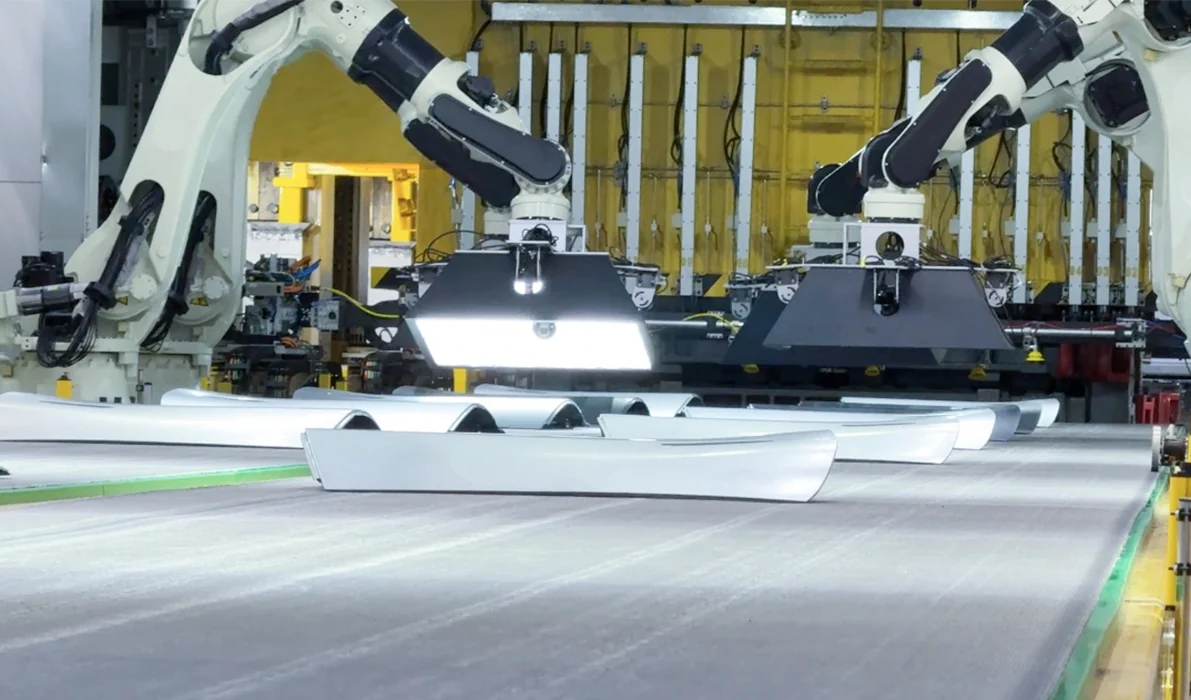
The application photograph shows access from several directions. The coverage and decision rules below are engineering guidance.
Swipe across the diagram to see all details →
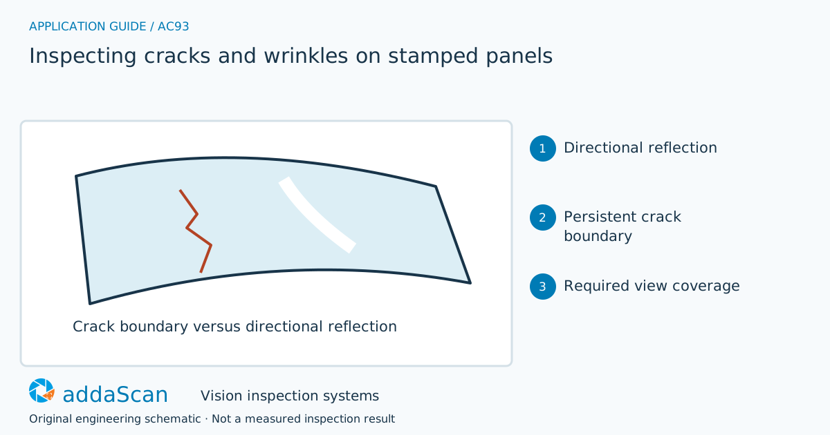
Surface reflections vary with illumination, while defect decisions require qualified evidence from labelled samples and complete required views. Original schematic; the photograph illustrates access rather than a measured detection result.
Select an image to view it at full size.
Make the defect visible before choosing the classifier
Curved reflective panels change appearance with viewing and lighting direction. Test directional illumination on known cracks, wrinkles and acceptable draw marks. Register the panel and retain a coverage map for folds, recesses and edges. A robot-mounted or multi-position camera can reach more regions but introduces pose repeatability, cycle coordination and image-to-part association responsibilities.
Define the visible defect classes and inspection regions with stamped-panel quality samples. A narrow crack, broad wrinkle and accepted draw mark can respond differently to light direction. Keep those labels tied to physical references so a classifier does not treat every bright line as the same fault. Include the surface condition expected at inspection, such as permitted oil or handling marks.
Build a coverage map showing which view resolves each region. Recesses and highly curved zones may require different lighting or access. A programmed camera pose is not proof that its intended region was acquired: confirm localisation, usable exposure and sequence completion. Missing required views should remain unresolved even when every available image looks acceptable.
Compare fixed cameras with qualified programmed viewpoints
Swipe across the table to compare all columns →
| Approach | Useful when | Limit or integration responsibility |
|---|---|---|
| Fixed cameras | Repeatable accessible regions | May require several views around curved surfaces. |
| Multiple programmed viewpoints | Recesses and large-panel coverage | Needs pose verification, sequence completion and part tracking. |
Fixed views simplify the acquisition sequence where the required regions are accessible. Programmed or robot-mounted views can add access but need pose checks and part-event association. Compare actual defect visibility and complete-region acquisition, including cycle constraints, rather than assigning a universal camera resolution or lighting angle.
A changing reflection is not automatically a crack
Illustrative scenario: a bright band disappears when illumination changes, while a known crack retains a meaningful boundary under a suitable view. Use the labelled samples to establish the decision, not brightness alone.
Hold a suspect panel with its region and image evidence. After changing a view, recheck the affected coverage and reference defects. Release requires valid observations of all specified regions; an omitted recess cannot inherit a pass.
After changing a camera or lighting pose, repeat both known defects and acceptable surface references in affected regions. Retain the original suspect-region image. A later image from another part cannot close a missed view in the first panel’s coverage map.
Challenge defect direction and missed panel views
Swipe across the table to compare all columns →
| Challenge sample or event | Expected behaviour to establish | Evidence to retain |
|---|---|---|
| Cracks at different orientations | Demonstrate visibility in at least the specified view. | Physical crack sample and direction, acquired lighting/view, located defect region and classification against the approved reference. |
| Wrinkles, draw marks and moving reflections | Retain correct classifications across normal finish variation. | Known wrinkle/draw-mark/reflection examples, views under changed illumination and the evidence used to separate their states. |
| Missed viewpoint or panel pose error | Return incomplete coverage and block release. | Panel event and pose, expected/completed view map, missing region and the valid reacquisition or independent disposition. |
Challenge defect directions and accepted forming texture across the required regions. Separate missed defects, false rejects and failed acquisitions in the report. Visible crack inspection should not be described as proof of hidden integrity or structural fitness.
Surface images cannot establish hidden structural integrity
Visible surface inspection does not establish hidden cracks, material properties or structural fitness.
Prepare labelled panels and the required coverage map
Share permitted photos or drawings, plus details of panel geometries, labelled defect sample examples, normal draw marks, cycle constraints and access around the fixture. Agree any physical sample arrangements after the initial assessment.
Surface defect detection defines visible surface-fault decisions and their limits. Access, panel condition and the view sequence determine the proposed inspection station.
Scratch detection on aluminium extrusions examines scratches versus acceptable extrusion texture. Stamped-panel curvature and forming marks need their own references and coverage study.
Use the cost and scope guide to understand the station boundary. An estimate depends on the required views, product presentation, exception handling and connection to the existing line. A similar camera does not establish the price of this application.
For line conditions around cracks and wrinkles across stamped-panel surfaces, see metal-component inspection.
Compare lighting, processing, interfaces and support in the HIKROBOT and other vision solutions guide. Agree sample testing, acceptance responsibilities and handover through the delivery process.