Application guide by addaScanCompare the inspection task, imaging conditions and validation steps with your own production line.
- Inspection focus
- O-ring nicks, protrusions and missing depth
- Primary theme
- Surface defect detection
- Decision evidence
- Raised material
- Trial priority
- Known nick and raised rubber
Keep a missing edge, raised material and dark appearance distinct
The original English schematic explains the observable features and the proposed decision. The tables below set out the conditions to test on your own line.
Swipe across the diagram to see all details →
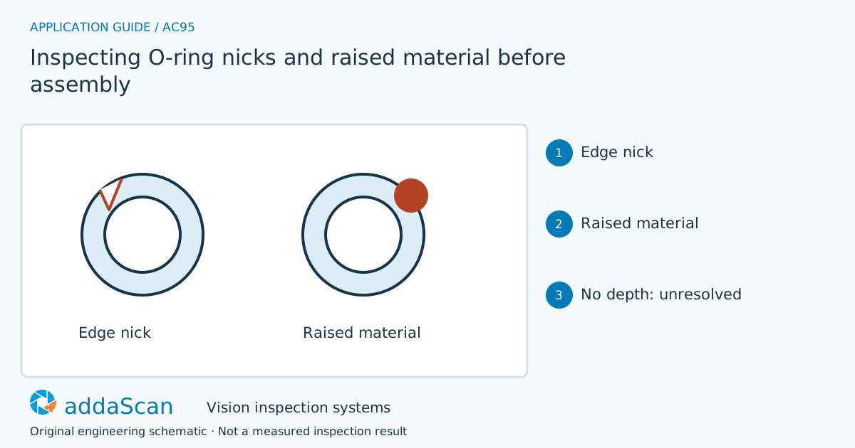
A nick, raised rubber and a dark unmeasured region have different meanings. Preserve the geometry and validity evidence for the affected ring segment. Original schematic; sealing performance is not tested.
Select an image to view it at full size.
Compare silhouette, directional shading and height evidence
A backlit silhouette can reveal edge nicks but misses some surface defects. Multiple lighting directions can reveal relief without providing a calibrated depth measurement. Three-dimensional profiles may measure geometry where the rubber returns usable data, but steep edges and dark areas can remain absent. Rotate or otherwise present the ring so that the specified circumference is covered without deforming it.
Define the inspected ring regions and the defect geometry. A nick removes material from an edge, while flash or raised rubber adds material; a dark patch can arise from texture or acquisition rather than either condition. Use physical defect references to establish what a contour image or height profile actually reveals.
Present the ring without stretching it into an unrepresentative shape. Rotation, light compression and support contact can change the visible outline or hide the inner edge. Track coverage around the required circumference and identify regions blocked by the fixture. An apparent complete circle in a fitted model does not fill the gaps in observed evidence.
Choose evidence for the specified O-ring defect
Swipe across the table to compare all columns →
| Approach | Useful when | Limit or integration responsibility |
|---|---|---|
| 2D silhouette and directional light | Edge nicks and visible surface relief | Does not inherently provide defect depth. |
| Profile measurement | Quantified raised or missing material | Requires valid returns, full coverage and a non-distorting fixture. |
Silhouette or directional-light imaging can reveal qualified edge defects. Profile evidence may help with raised geometry where the material provides valid returns. Compare the approaches on the smallest relevant physical defect and acceptable texture, keeping missing depth distinct from material loss.
A dark patch without valid depth remains unresolved
Illustrative scenario: a dark patch coincides with a hole in the depth data. Mark it unmeasurable rather than assigning a nick depth.
Re-present the ring and acquire a valid observation, retaining the initial coverage failure. If material loss is then confirmed against the sample criteria, isolate the ring. Release only after all required circumference regions have valid decisions under the agreed support conditions.
Reorient an unresolved ring only through a qualified presentation that preserves its identity and does not create further deformation. Review a confirmed defect separately from a missing view; a second attractive contour should not automatically erase earlier evidence of a nick.
Challenge ring rotation and handling deformation
Swipe across the table to compare all columns →
| Challenge sample or event | Expected behaviour to establish | Evidence to retain |
|---|---|---|
| Known nick and raised rubber | Record location and valid supporting image or profile. | Labelled nick/raised-rubber sample, ring-region position, observed contour or profile and defect-specific decision. |
| Dark patch without depth | Return unmeasurable rather than zero or missing material. | Dark-region image, raw/invalid depth evidence, acquisition condition and unresolved-result disposition. |
| Rotated and lightly deformed ring | Check coverage and fixture-induced shape changes. | Ring orientation and support contact, circumferential coverage, deformation state and accepted reacquisition. |
Rotate reference defects through the required coverage and vary the permitted handling condition. Include acceptable surface texture. Where sealing or compression performance matters, specify an independent test rather than inferring it from visible ring geometry.
Visible geometry cannot establish sealing performance
Appearance and geometry do not prove sealing performance or compound properties.
Prepare labelled O-ring defects and presentation limits
Share permitted photos or drawings, plus details of ring sizes, compounds, defect sample examples, permissible deformation and any dimensional limits. Agree any physical sample arrangements after the initial assessment.
Surface defect detection supports the visible O-ring defect definition. Qualify the material response and fixture coverage before choosing intensity or profile-based inspection.
Distinguishing missing, reversed and correctly fitted cap liners checks cap-liner assembly states. An O-ring can be visibly defect-free yet still require a separate check of its later installation.
Use the cost and scope guide to understand the station boundary. An estimate depends on the required views, product presentation, exception handling and connection to the existing line. A similar camera does not establish the price of this application.
Compare lighting, processing, interfaces and support in the HIKROBOT and other vision solutions guide. Agree sample testing, acceptance responsibilities and handover through the delivery process.