Application guide by addaScanCompare the inspection task, imaging conditions and validation steps with your own production line.
- Inspection task
- Compressor grinding-defect inspection
- Decision focus
- compressor grinding-defect inspection
- Station planning
- Compare lighting directions on the same surface region
- Illustrative scenario
- a dark streak is not automatically a scratch
Locate grinding marks on the inspected metal surface
The application images show the physical product and imaging conditions. The engineering diagram below explains the inspection logic and recovery decisions.
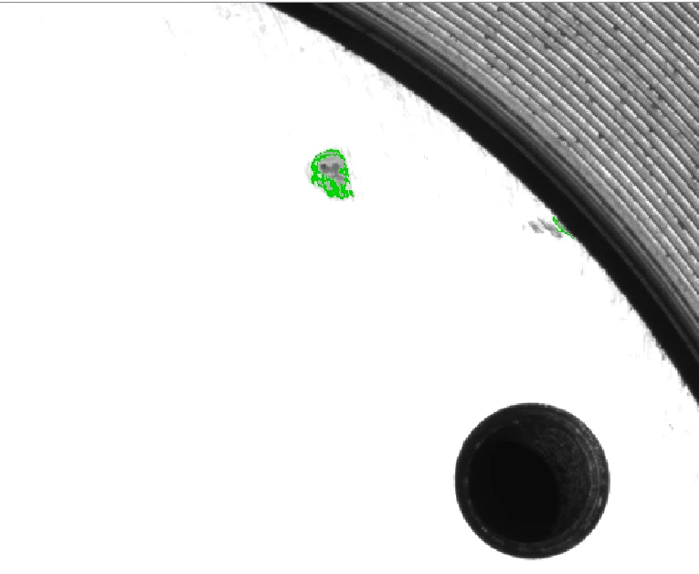
Selected machining-surface region with the original defect overlay; software controls are outside the crop.
Select an image to view it at full size.
Distinguish normal grinding texture from surface damage
Swipe across the table to compare all columns →
| Condition | Approach to evaluate | Selection check |
|---|---|---|
| Visible damage or unground patches | Evaluate controlled 2D surface imaging. | Compare defects with permitted machining texture. |
| Shiny face with angle-dependent features | Evaluate several illumination directions. | Keep the same defect visible through positioning variation. |
| Specified geometric flatness | Assess calibrated 3D or contact metrology. | A binary appearance result is not a height measurement. |
Compare lighting directions on the same surface region
Register the part to its physical features and mask holes, edges and deliberately unground regions that are outside the inspection requirement. Compare the same valid surface under different illumination directions. Normal grinding marks may brighten together as the light direction changes; a local scratch or raised chip can respond differently. Preserve the registered views so the comparison concerns the same location.
A rule-based texture check is useful where finish is consistent and defects have stable contrast. A trained model may help with normal process variation, but requires examples from acceptable tooling and finish conditions. Neither approach substitutes for a flatness measurement. If the requirement is dimensional rather than visible appearance, assign it to an appropriate measurement method with its own reference.
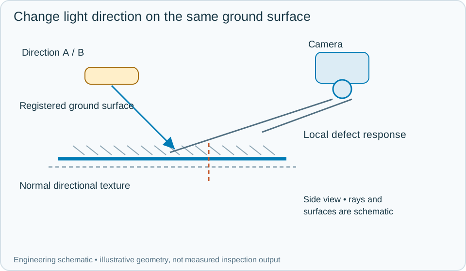
On a small screen, scroll across the diagram to inspect the labels.
Worked example: a dark streak is not automatically a scratch
In an illustrative part, a dark streak follows the grinding direction. Under the second light, it behaves like the surrounding accepted tool marks and falls within the approved texture pattern. Keep it as an acceptable finish example rather than adding an arbitrary brightness exception.
Another local feature stays distinct from the normal texture and interrupts it. Preserve the registered crops and classify it using the agreed surface-defect rule. A loose particle may cast a similar feature; route the part through an authorised cleaning and reinspection step if that is permitted. Retain both attempts so a removable contaminant is distinguishable from permanent damage. If the part cannot be located or a required surface remains hidden, return incomplete inspection and hold it instead of evaluating a shifted region.
Swipe across the table to compare all columns →
| Observed evidence | Inspection decision | Action and retained record |
|---|---|---|
| A directional streak follows approved grinding texture under both registered illumination views. | Potential normal finish; evaluate against the accepted texture set. | Retain both views and the process variation represented by the sample. Do not introduce a global brightness exception from one image. |
| A local feature interrupts the accepted texture and persists after approved cleaning. | Permanent surface-defect candidate. | Keep before-and-after images and the registered surface region, apply the agreed defect rule and confirm the part's physical disposition. |
| The inspection mask drifts onto an intentional hole or edge. | Invalid localisation, not a confirmed grinding defect. | Hold the part, restore its reference and repeat inspection. Check fixture and lighting stability before retraining the appearance model. |
Use false rejects to improve the right layer
When good parts begin failing after a grinding-wheel change, compare the new accepted finish with the validation set. First exclude light movement, dirty optics and localisation drift. Only then consider expanding the approved texture representation; keep real scratches and residual chips in the regression sample set.
Record the surface zone, illumination view, defect evidence and final disposition. Linking these records to the available machining batch can support process investigation, but the image alone does not establish the cause of a grinding fault.
Swipe across the table to compare all columns →
| Challenge | What to verify |
|---|---|
| Different normal machining marks | Count false rejects on acceptable finish. |
| Small defects near holes | Verify masks do not hide required inspection areas. |
| Rotated or shifted part | Check localisation before defect segmentation. |
| Borderline surface samples | Agree their classification against the actual specification. |
Grinding finishes and defect samples to compare
Provide the ground-face drawing, acceptable texture samples, defects and any separate dimensional flatness requirement.
Use the machine vision lighting guide to develop the next step.
Define the wider inspection responsibility in surface defect detection.
Use the machining inspection guide to distinguish surface-finish inspection from the dimensional checks required on the same component.
Use the optical and recovery challenges above when applying the architecture choices in vision-system comparison guide.
Scope and budget
The vision system cost guide helps separate lighting and surface classification from any additional dimensional measurement.
Testing and handover
Include acceptable grinding textures and reference defects in the testing and handover process, with flatness tested by the agreed measurement method.