Application guide by addaScanCompare the inspection task, imaging conditions and validation steps with your own production line.
- Inspection focus
- Exposed copper inside a protected winding region
- Primary theme
- Surface defect detection
- Decision evidence
- Protected winding region
- Trial priority
- Normal exposed terminal
Distinguish protected winding regions from intended terminals
The original English schematic explains the observable features and the proposed decision. The tables below set out the conditions to test on your own line.
Swipe across the diagram to see all details →
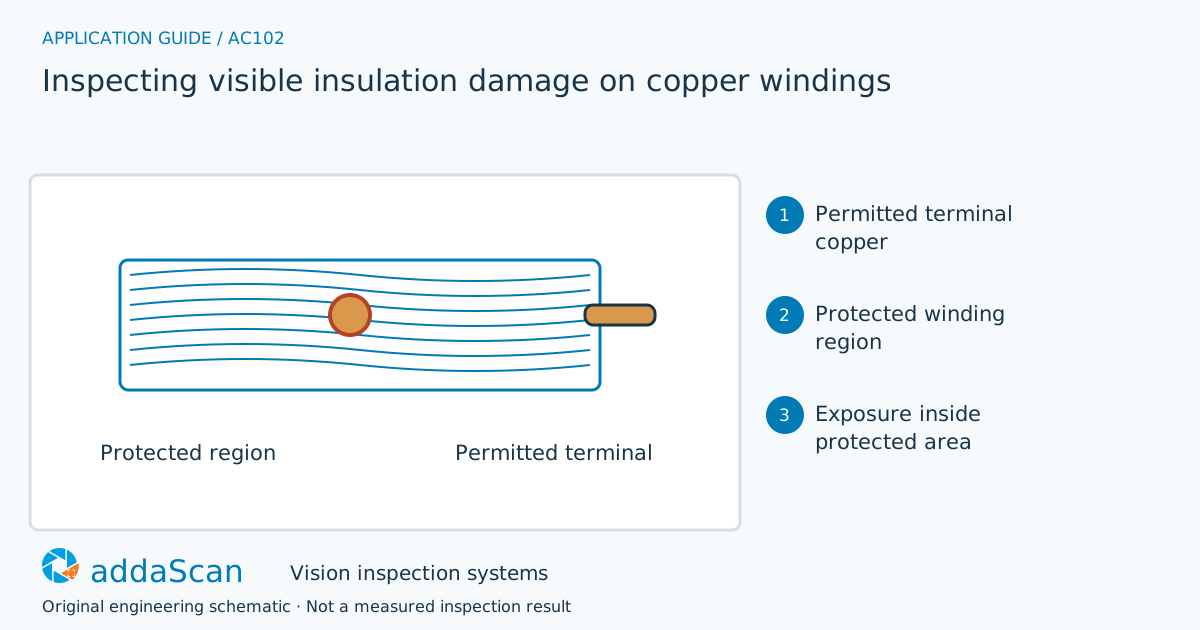
Exposed conductor must be interpreted relative to the winding’s protected and terminal regions. Hidden surfaces remain outside the optical conclusion. Original schematic; electrical insulation performance is not measured.
Select an image to view it at full size.
Use functional regions to interpret bright features
Copper curvature produces strong reflections, and insulation colours vary with material and lighting. Register the winding or component and separate terminal regions from the required insulated surface. Use labelled samples to test whether a suspected break remains distinguishable under permitted orientations. Hidden turns remain outside optical coverage; adding a classifier cannot recover a surface the camera never sees.
Map where insulation is required and where exposed conductor is intentional. A terminal or connection region can resemble damage if the model only looks for copper-coloured pixels. Locate the winding and apply the approved protected-region definition before classifying an exposed surface. Keep location errors separate from actual insulation faults.
Copper reflections and curved turns can hide coating damage or create misleading bright features. Test representative coated, exposed and damaged references under the proposed viewing directions. Record the required surface coverage, including turns obscured by neighbouring wire or the assembly fixture. A clean visible side does not establish the condition of the hidden side.
Select views around curvature and surface reflections
Swipe across the table to compare all columns →
| Approach | Useful when | Limit or integration responsibility |
|---|---|---|
| Global bright-spot detection | Simple visual screening | Can reject intended exposed terminals. |
| Region-aware surface inspection | Exposed copper where insulation is required | Needs registration, accepted region definitions and suitable lighting. |
Use intensity or colour evidence where the required coating condition remains distinguishable from normal surface variation. Complementary views may add coverage, but some internal turns remain inaccessible. Specify that boundary rather than interpreting an overall appearance score as complete insulation acceptance.
Exposed copper is acceptable only in the specified region
Illustrative scenario: a bright feature lies at an intentionally exposed terminal and is accepted under that region rule. A similar feature inside the protected winding area is held for assessment.
Retain its location and images, then recheck the same area after repair and link the result to the required electrical tests. Release only when the visible region is resolved and the separately required test records are complete.
After rework or repositioning, reacquire the affected protected regions and preserve the original defect location. Any required electrical test retains its own identity and outcome; a visual pass should not erase an independent electrical failure.
Challenge known damage and hidden winding surfaces
Swipe across the table to compare all columns →
| Challenge sample or event | Expected behaviour to establish | Evidence to retain |
|---|---|---|
| Normal exposed terminal | Do not label it insulation damage. | Winding datum, approved exposed-terminal region, observed conductor location and the correct region-specific acceptance. |
| Known damage inside protected turns | Retain location and classification evidence. | Independently labelled damage within protected turns, required-view images, defect location and containment decision. |
| Occluded winding surface | State incomplete coverage and use the agreed additional assessment. | Expected surface-coverage map, occluded turns, attempted alternate view and the unresolved or independent inspection route. |
Include acceptable bare terminals, damaged protected turns and reflecting but intact coating. Report observed defects separately from inaccessible regions. Correlate with other quality tests only through an agreed validation study.
Visible insulation checks do not replace electrical testing
Visible inspection cannot prove dielectric integrity or detect every hidden insulation fault.
Prepare winding drawings and labelled damage samples
Share permitted photos or drawings, plus details of winding variants, terminal boundaries, labelled damage sample examples, viewing access and electrical-test linkage. Agree any physical sample arrangements after the initial assessment.
Surface defect detection helps define the visible coating fault and qualified coverage. Specify electrical acceptance separately from the optical station.
Scratch detection on aluminium extrusions separates scratches from normal surface texture. Copper windings additionally require region-specific insulation rules and explicit coverage limits.
Use the cost and scope guide to understand the station boundary. An estimate depends on the required views, product presentation, exception handling and connection to the existing line. A similar camera does not establish the price of this application.
Compare lighting, processing, interfaces and support in the HIKROBOT and other vision solutions guide. Agree sample testing, acceptance responsibilities and handover through the delivery process.