Application guide by addaScanCompare the inspection task, imaging conditions and validation steps with your own production line.
- Inspection focus
- Pin height with complete position coverage
- Primary theme
- Dimensional measurement
- Decision evidence
- Rear row occluded
- Trial priority
- High, low and bent pins
Every required pin needs a valid height against one datum
Reference imagery and an original English schematic explain the observable features and the proposed decision. The tables below set out the conditions to test on your own line.
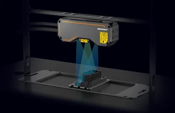
Application rendering showing profile acquisition geometry; it is not a captured pin-height result.
Swipe across the diagram to see all details →
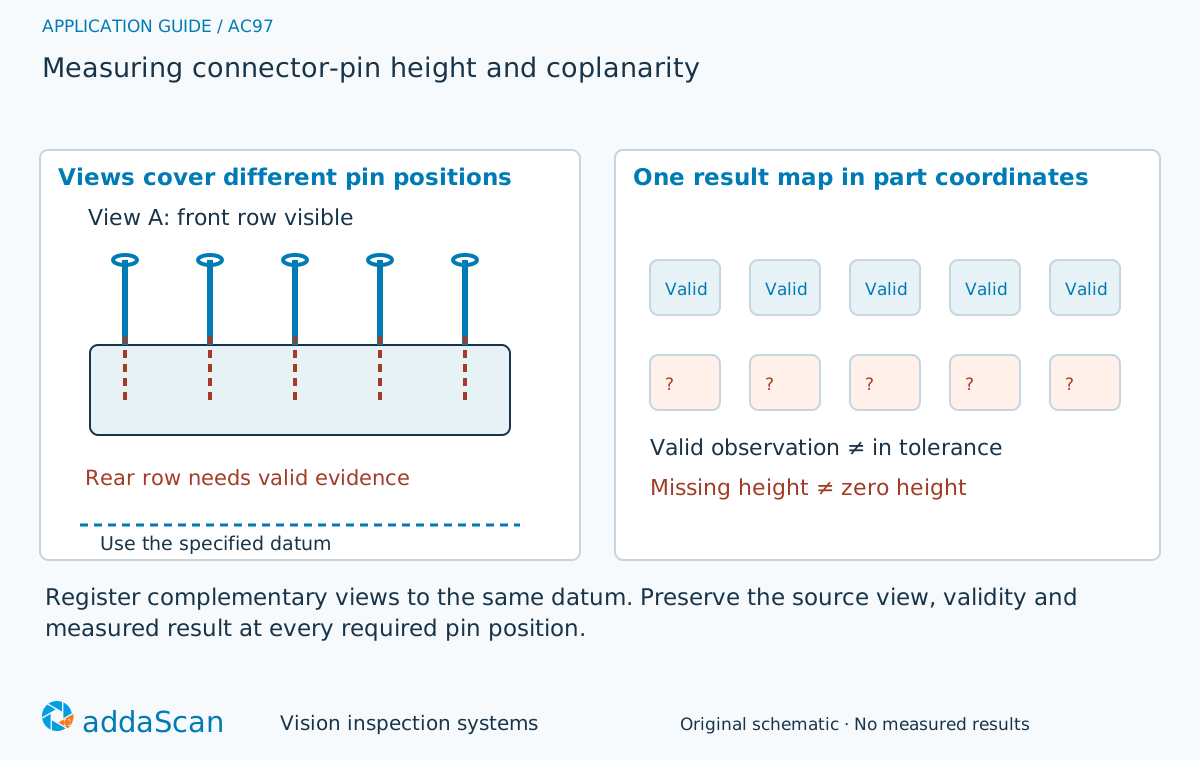
Measured front-row pins do not resolve an occluded rear row. Keep a validity state at every required position and register complementary views to the same datum. Original schematic; the adjacent rendering is an acquisition arrangement, not measured pin heights.
Select an image to view it at full size.
Use the housing datum without hiding individual high pins
Locate the connector variant and expected pin map. Establish the reference plane from the specified housing or measurement datum rather than fitting a plane through all pin tips indiscriminately. Reflective tips and row occlusion may require an additional viewing direction. When combining views, confirm coordinate registration and identify which sensor supplied each result.
Specify the quantity being evaluated. Individual pin height relative to a housing datum and coplanarity of a group of pin tips are related but different outputs. The product requirement must define the reference and evaluation method; fitting a plane through every tip can conceal a group tilt or distribute the effect of one abnormal pin across the result. Keep the located pin positions and reference features with the measurements.
Create a position map for each connector variant. Each required position needs a valid observation, a height result and a decision. A missing optical return may be caused by rear-row occlusion, a reflective tip or loss of focus. It cannot be entered as zero height or removed from the denominator of a complete-connector result.
When another view is added, register it into the same qualified coordinates. Where both sensors see a pin, compare their results and define how a disagreement is resolved. Do not select whichever result happens to be closer to nominal. Where only one view sees a pin, retain which view supplied it and whether the reference registration remained valid for that acquisition.
Resolve occluded rows before combining profile results
Swipe across the table to compare all columns →
| Approach | Useful when | Limit or integration responsibility |
|---|---|---|
| Single profile view | Exposed tips with reliable returns | Test rear-row occlusion across the whole connector. |
| Additional or complementary views | Hidden or reflective tips | Needs common coordinates and explicit per-pin result fusion. |
Start with the required pin map and test the worst accessible row. A single profile is sufficient only if it supplies valid evidence for every specified position under the allowed presentation. Complementary views can address occlusion, but introduce registration and synchronisation work. Mechanical presentation changes may expose the tips more reliably than adding a sensor aimed through the same obstruction.
An empty depth result is not a low pin
Illustrative scenario: front-row pins have valid heights while the rear row produces no depth. Block the part result and acquire the missing positions from a qualified additional view.
If they remain unresolved, use the agreed independent measurement route. Retain per-pin validity and height values. Release only when all required positions are measured against the correct datum and fall within the approved limits.
Reacquiring the rear row does not authorise mixing it with front-row data from another connector. Keep the same part event and a valid reference transform, or repeat the complete measurement. If the independent route resolves the missing positions, record its method and results rather than converting the original invalid scan into an apparently complete optical scan.
Challenge datum shifts and overlapping sensor views
Swipe across the table to compare all columns →
| Challenge sample or event | Expected behaviour to establish | Evidence to retain |
|---|---|---|
| High, low and bent pins | Compare positional measurements with reference evidence. | Independent values for known high, low or bent pins, measured tip regions, per-pin heights and the resulting decisions. |
| Rear row missing depth | Return incomplete measurement, not zero height. | Expected position map, source view, missing rear-row region, complementary acquisition and registration evidence for recovered pins. |
| Wrong variant or datum tilt | Prevent an apparently good fit from releasing the wrong pin map. | Connector variant, datum features, calibration version, pose change and complete position map under the corrected recipe. |
Separate repeated scanning of a stationary connector from repeat placement in the fixture. Challenge reflective finishes, allowed housing tilt, row occlusion and sensor disagreement. Use independent references that can resolve the specified pin geometry and compare measurement variation with the acceptance tolerance. A complete result needs every required position, a valid datum and an agreed treatment of measurement uncertainty near the limit.
Pin geometry does not prove electrical contact
Pin geometry does not establish electrical contact resistance or connector function.
Define the pin map and reference measurement method
Share permitted photos or drawings, plus details of pin drawings, datum definitions, reference measurements, reflective finishes and fixture access. Agree any physical sample arrangements after the initial assessment.
Dimensional measurement covers datum selection and measurement validation for pin geometry. A 3D pin-height station is a separate scope from a basic component-presence check.
PCBA solder inspection with 3D height provides a related assembly inspection example. Preserve the distinction between a component being fitted and every required pin satisfying its geometric requirement.
Use the cost and scope guide to understand the station boundary. 3D pin-height measurement is explicitly outside the existing assembly-verification budget; include profiling, registration and reference validation separately.
Compare lighting, processing, interfaces and support in the HIKROBOT and other vision solutions guide. Agree sample testing, acceptance responsibilities and handover through the delivery process.