Application guide by addaScanCompare the inspection task, imaging conditions and validation steps with your own production line.
- Inspection focus
- Cut edge relative to the printed label
- Primary theme
- Dimensional measurement
- Decision evidence
- Registered artwork
- Trial priority
- Aligned colours with displaced cut
The cut edge must be measured against the printed reference
The original English schematic explains the observable features and the proposed decision. The tables below set out the conditions to test on your own line.
Swipe across the diagram to see all details →
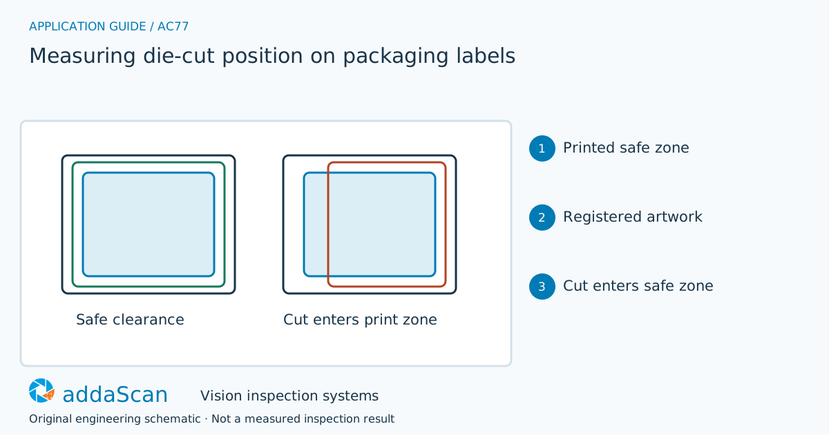
Cut position is measured relative to the artwork on the same repeat. Correct colour registration and a moving web edge do not independently establish cut-to-print alignment. Original schematic.
Select an image to view it at full size.
Treat print registration and cutting registration as separate offsets
Locate a stable print reference and the physical die-cut edge in the same coordinate system. Depending on the liner and material, transmitted illumination may reveal cuts that reflected light misses. Web wander changes both positions together; the relative offset is the useful value. Encoder sampling must remain valid through acceleration so machine-direction distortion does not appear as cutting error.
Define the artwork feature used as the cutting reference and the physical boundary that represents the cut. A print-to-print registration mark can remain correct while the cutting tool shifts. Where a liner, waste matrix or reflective edge obscures the actual cut, test whether the proposed view observes the boundary that the drawing specifies rather than a nearby contrast line.
Express cut position relative to the located artwork on the same repeat. Whole-web lateral movement should change the absolute coordinates of both features while leaving their relative offset largely unchanged. A genuine tool displacement changes that relationship. Keep cross-web offset and repeat-direction phase separate so the operator can identify which adjustment is relevant.
Separate print registration from cutting-tool position
Swipe across the table to compare all columns →
| Approach | Useful when | Limit or integration responsibility |
|---|---|---|
| Print-only registration | Colour alignment | Cannot prove physical cut position. |
| Edge plus print measurement | Cut-to-artwork clearance | Needs cut visibility, web coordinates and a defined safe margin. |
A fixed image can measure a presented label repeat when the required edges are exposed. Continuous acquisition needs qualified material-position sampling and repeat association. Compare the two at the same field and boundary resolution, including acceleration and tool changes; print colour alignment alone is not a cut-position reference.
Aligned print colours can hide a displaced cut
Illustrative scenario: printed colours align, but the cut edge enters the specified artwork clearance. Mark the affected web interval and hold conversion of that material.
Stabilise tension, check the tool phase and verify the displacement reference. After adjustment, capture the cut-to-print relationship again using approved samples. Release the new interval only after the datum and limits are valid; keep the startup material separately identified.
After adjusting the tool, identify the first material produced under the new setting and verify the relative cut position before releasing that segment. Do not reclassify material already cut under the earlier setting simply because the current image has improved.
Challenge web wander and changes in tool phase
Swipe across the table to compare all columns →
| Challenge sample or event | Expected behaviour to establish | Evidence to retain |
|---|---|---|
| Aligned colours with displaced cut | Detect cutting error independently. | Artwork reference, located cut boundary, colour-registration result and independent cut-to-print offset for the affected repeat. |
| Whole-web lateral movement | Preserve relative clearance if both features move together. | Both absolute edge/reference coordinates, relative displacement and the recorded whole-web shift. |
| Tool adjustment and acceleration | Map uncertain material to a retained roll interval. | Tool-setting change, repeat/material coordinates, acceleration state and first-off measurements after adjustment. |
Use displaced cuts with correctly registered colours, then move the whole web without changing the cut relationship. Repeat after tool adjustment and tension changes. Where closed-loop correction is proposed, verify the sign and delay independently before allowing measured error to command an adjustment.
Cut-position evidence does not establish every label property
Cut position does not establish adhesive performance, liner release or downstream application quality.
Define the artwork datum and cutting tolerance
Share permitted photos or drawings, plus details of die lines, artwork datums, cut-clearance limits, liner sample examples and web-speed transitions. Agree any physical sample arrangements after the initial assessment.
Dimensional measurement supports the calibrated edge-to-reference measurement. Define the exposed cut, repeat tracking and any correction interface before selecting acquisition hardware.
Roll-label print and registration inspection checks missing print and print registration. Keep those outcomes separate from the die-cut offset measured here.
Use the cost and scope guide to understand the station boundary. Continuous-material imaging, encoder integration and calibrated cut-position measurement require a separate line-scan or measurement scope.
For line conditions around cut edge relative to the printed label, see plastics and packaging inspection.
Compare lighting, processing, interfaces and support in the HIKROBOT and other vision solutions guide. Agree sample testing, acceptance responsibilities and handover through the delivery process.