Application guide by addaScanCompare the inspection task, imaging conditions and validation steps with your own production line.
- Inspection focus
- Thickness from opposing surfaces in one coordinate system
- Primary theme
- Dimensional measurement
- Decision evidence
- Lower surface profile
- Trial priority
- Known thickness moved vertically
Measure surface separation rather than top-side motion
The original English schematic explains the observable features and the proposed decision. The tables below set out the conditions to test on your own line.
Swipe across the diagram to see all details →
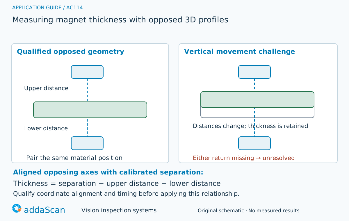
Thickness is the separation of corresponding upper and lower surfaces in a calibrated geometry. Part motion, mismatched positions or a missing return must not be reported as a material change. Original schematic; no achieved accuracy is implied.
Select an image to view it at full size.
Calibrate sensor separation and synchronise the surfaces
Place upper and lower observations in a common calibrated coordinate system. The thickness calculation depends on the sensor geometry and valid surface measurements, not simply on adding two arbitrary height outputs. When the part moves, corresponding samples must describe the same material location. Reflective coatings, edge chamfers and missing returns need explicit exclusion or invalid-measurement rules.
Define the physical thickness direction and the surfaces to be compared. For aligned opposing sensors with a calibrated separation, thickness can be derived from that separation and the two distances to the material surfaces. This relationship assumes the distances describe corresponding locations in the agreed geometry. Arbitrarily adding two sensor height outputs does not establish thickness.
Calibrate the two observations into a common reference and check their relative orientation. If the upper and lower profiles are laterally offset, they can sample different locations on a tapered or chamfered part. A reference of known geometry should therefore be translated through the usable field, not tested only at one central position. Keep edge exclusions explicit so a chamfer is not compared with a full-thickness region on the opposite side.
Motion introduces another association problem. Time or encoder alignment must ensure that upper and lower samples belong to the same material position. A vertical movement test checks whether common motion cancels as intended; a translation test checks whether the profiles still pair correctly. Stable output alone is insufficient if smoothing or stale data conceals the movement.
When one support reference or opposed profiles are suitable
Swipe across the table to compare all columns →
| Approach | Useful when | Limit or integration responsibility |
|---|---|---|
| Single-side height | Thickness against a verified stable support | Sensitive to lift, debris and support movement. |
| Opposed surface profiles | Thickness despite permitted vertical movement | Needs common coordinates, synchronisation and two valid surface results. |
A single-sided measurement can be appropriate where the support surface is qualified and its position remains known. Opposed measurement removes dependence on that support only when both surfaces are valid and their coordinates and timing remain qualified. Compare the added access, shielding, calibration and maintenance requirements with the actual need to tolerate part motion.
An upward-moving magnet should not become thicker
Illustrative scenario: a magnet moves upward without changing thickness. The top-side distance changes, but the calibrated separation of its upper and lower surfaces should remain stable.
If the derived thickness changes, investigate coordinate alignment and acquisition timing before adjusting the tolerance. Recalibrate and rescan invalid regions. Release only when the thickness result and its measurement uncertainty support the agreed decision.
Invalidate the paired result if either side loses its surface return or if the reference geometry is outside its qualified state. Recalibrate after a mounting change and retain the earlier configuration for investigation. Do not use the last valid lower profile to complete a newer upper profile, even if that produces a plausible nominal thickness.
Challenge timing, alignment and both surface returns
Swipe across the table to compare all columns →
| Challenge sample or event | Expected behaviour to establish | Evidence to retain |
|---|---|---|
| Known thickness moved vertically | Confirm thickness stability despite changing absolute height. | Reference thickness, controlled vertical displacement, upper/lower raw distances, common-coordinate result and both validity states. |
| Chamfer, coating and missing return | Record valid measurement region and invalid samples. | Surface finish and chamfer region, upper/lower material-position pairing, missing-return map and unresolved-result disposition. |
| Reference artefact and repeated scans | Evaluate repeatability and uncertainty before release limits are applied. | Independent reference values, calibration version, stationary and repeated-placement results, timing checks and observed drift. |
Use independent thickness references appropriate to the required uncertainty. Challenge vertical movement, lateral travel, rotation within the permitted range, reflective coating and interrupted acquisition. Repeat removal and replacement separately from stationary scans. Review drift after a representative operating period and agree the reference-check routine. Release decisions must use a valid paired measurement and a defined rule near the tolerance boundary; the diagram does not claim achieved accuracy.
Thickness does not establish magnetic performance
The underlying reference is a measurement-method example. No production throughput or achieved accuracy is claimed here; those require a station-specific study.
Define the opposed-sensor measurement geometry
Share permitted photos or drawings, plus details of magnet dimensions, coating, reference thickness values, motion conditions and the required uncertainty relative to tolerance. Agree any physical sample arrangements after the initial assessment.
Dimensional measurement covers calibration, uncertainty and acceptance of the derived thickness. Opposed profiling requires a separate optical and mechanical scope from a standard single-view measurement station.
Checking rivet presence and height on sunroof frames discusses another geometric check. Reuse the principle of a defined datum, while qualifying the two-sided synchronisation required here.
Use the cost and scope guide to understand the station boundary. Opposed profilers, synchronisation and common-coordinate calibration require separate pricing from a single-view station.
Compare lighting, processing, interfaces and support in the HIKROBOT and other vision solutions guide. Agree sample testing, acceptance responsibilities and handover through the delivery process.