Application guide by addaScanCompare the inspection task, imaging conditions and validation steps with your own production line.
- Inspection focus
- Width change versus lateral web movement
- Primary theme
- Dimensional measurement
- Decision evidence
- Width stays constant
- Trial priority
- Parallel edge shift
Track edge separation and web centre as separate quantities
The original English schematic explains the observable features and the proposed decision. The tables below set out the conditions to test on your own line.
Swipe across the diagram to see all details →
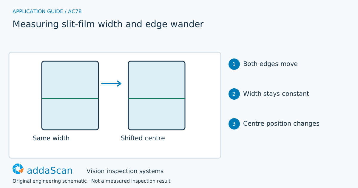
When both edges move together their separation can remain constant. Report width and lateral position separately, and do not calculate a fresh width from one missing edge. Original schematic.
Select an image to view it at full size.
Track both edges in the same calibrated section
Calculate width from the distance between left and right edges; use their centre position to describe lateral movement. Measuring the edges at different longitudinal positions can confuse diagonal travel or a local notch with width variation. Transparent film needs contrast against the background, and curled edges may change the apparent optical boundary. Establish the measurement plane and check the encoder-to-roll-length relationship.
Define the left and right material boundaries and measure them at the same longitudinal location. Their separation describes width; their position relative to the line reference describes lateral wander. Two independently acquired edges require a common calibrated coordinate system and material-position association. A width calculated from different repeats can look plausible while describing no real cross-section.
Film curl, translucency and flutter can make the visible edge move without a corresponding material-width change. Test support, illumination and exposure with the actual edge condition. If one edge disappears or folds out of the qualified plane, preserve the last valid record as history rather than using it to complete a new measurement.
Choose an edge arrangement that covers the width range
Swipe across the table to compare all columns →
| Approach | Useful when | Limit or integration responsibility |
|---|---|---|
| One edge sensor | Web guiding against a reference | Cannot distinguish width change from movement alone. |
| Two-edge camera measurement | Width and centre position | Needs simultaneous calibrated edges and a valid material plane. |
One wide-field view can simplify edge association if it resolves the required boundaries. Separate edge views can preserve detail over a larger width but add calibration and synchronisation responsibilities. In either layout, compare width and centre-position outputs independently against reference changes.
A sideways shift is not automatically a width change
Illustrative scenario: both edges shift towards the operator side by a similar amount. Keep the width result acceptable if it remains within the agreed limits, but raise the separate position condition.
After an edge-guide correction, verify both width and centre position. If one edge disappears, mark that roll interval unmeasurable and isolate it as agreed. Resume valid measurement only after both edges and the length reference are recovered.
After a stop or thread-up, reacquire both edges and the material-position reference before resuming width acceptance. A correction for wander must not be used to hide a genuine slit-width change; record which output drove any operator or controller adjustment.
Challenge one-edge movement and curled-film restarts
Swipe across the table to compare all columns →
| Challenge sample or event | Expected behaviour to establish | Evidence to retain |
|---|---|---|
| Parallel edge shift | Stable width with changing centre position. | Left/right coordinates at one material location, calculated width, centre shift and the unchanged reference-width check. |
| One edge moves while the other stays | Identify the actual width change. | Fixed-edge and moved-edge observations, independent width reference and separate width/wander decisions. |
| Curled or lost edge during restart | Retain the affected length and an invalid-measurement state. | Curl or missing-edge image, invalid measurement interval, restart association and the first complete two-edge result. |
Move both edges together, then change only one edge, and finally remove a usable edge observation. These challenges distinguish true width change, wander and invalid acquisition. Repeat through the permitted acceleration and film-tension range.
Width alone does not describe film quality
Optical width does not establish thickness or tensile properties. Edge curl may need mechanical control before measurement is meaningful.
Define the film edges and material-position reference
Share permitted photos or drawings, plus details of film opacity, nominal widths and tolerances, guide behaviour, edge defects and encoder details. Agree any physical sample arrangements after the initial assessment.
Dimensional measurement defines the edge measurement and calibration. The film support and the common material reference are as important as sensor resolution.
Transparent film defect inspection addresses holes, specks and wrinkles in film. Those surface defects remain distinct from calibrated width and edge-position outputs.
Use the cost and scope guide to understand the station boundary. Film-width acquisition, edge presentation and encoder integration must be priced for the material; standard camera bands are not a web-system quotation.
For line conditions around width change versus lateral web movement, see plastics and packaging inspection.
Compare lighting, processing, interfaces and support in the HIKROBOT and other vision solutions guide. Agree sample testing, acceptance responsibilities and handover through the delivery process.