Application guide by addaScanCompare the inspection task, imaging conditions and validation steps with your own production line.
- Inspection focus
- Tile bow measured against the specified support
- Primary theme
- Dimensional measurement
- Decision evidence
- Bowed tile surface
- Trial priority
- Raised corner and bowed centre
Show the support before interpreting tile height
The original English schematic explains the observable features and the proposed decision. The tables below set out the conditions to test on your own line.
Swipe across the diagram to see all details →
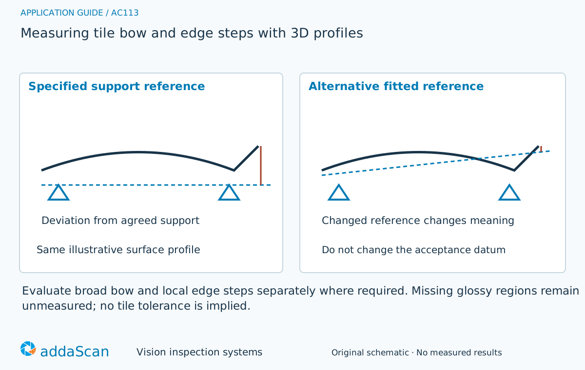
Evaluate the same tile against the reference required by its specification. A best-fit plane may reduce the apparent corner deviation compared with the defined support datum. Original comparison schematic; no universal tile tolerance or measured result is shown.
Select an image to view it at full size.
Choose the datum before processing the height map
Define how the tile is supported, which regions establish the datum and which deviations are evaluated. Conveyor vibration, tile tilt and surface reflectivity affect profile acquisition. Keep broad bow and local edge steps as separate outputs where the specification requires them. A pleasing flattened display is not necessarily the correct dimensional evaluation.
Write the measurement definition before configuring surface flattening. Identify the support locations, tile orientation, datum construction and the regions where bow or an edge step is evaluated. The customer’s product requirement determines these choices. A whole-surface best-fit plane may be useful for descriptive comparison, but it should not silently replace a support-based requirement.
Keep broad curvature and local edge discontinuity as separate features where required. A small group of high points near a corner can change a fitted plane; a local step may disappear if the surface is smoothed too strongly. Preserve the original profile and the evaluation settings so the result can be reproduced from the same valid data. Do not report a reconstructed missing corner as a measured surface.
On a moving line, determine whether the support condition during acquisition matches the intended measurement. Roller transitions, vibration or tile tilt can contribute to the observed height. Repeat scans on a controlled reference arrangement before attributing all variation to the tile. Glossy glaze and dark regions can also create invalid profile areas, which must remain distinct from low points.
A best-fit plane and a support datum answer different questions
Swipe across the table to compare all columns →
| Approach | Useful when | Limit or integration responsibility |
|---|---|---|
| Whole-surface best fit | Descriptive surface comparison | May not match the specified support-based bow measurement. |
| Defined support-datum profile | Bow and edge steps against product criteria | Requires repeatable support and uncertainty evaluation. |
Choose support-datum evaluation when the acceptance definition is tied to that reference. Use a whole-surface fit only where its meaning is appropriate and explicitly agreed. Both methods still need valid data over the specified regions. Compare fixture-based and conveyor acquisition using the same physical tile and definition before deciding whether the line presentation can support the requested decision.
Re-evaluate a raised corner against the agreed datum
Illustrative scenario: a whole-surface plane fit makes a raised corner appear less severe. Re-evaluate the same valid profile against the agreed support datum and hold the tile if that result exceeds the approved limit.
Check support repeatability and reacquire any missing regions. Release only with complete required coverage, the correct datum method and tolerances from the applicable product requirement.
If support or datum validity is lost, reacquire under the agreed conditions. If the profile is valid but the wrong evaluation was applied, preserve the original result and record the corrected method. A genuine geometric failure must not be cleared merely by selecting a different plane fit; changing the acceptance definition requires an authorised product decision.
Repeat support placement and challenge missing profiles
Swipe across the table to compare all columns →
| Challenge sample or event | Expected behaviour to establish | Evidence to retain |
|---|---|---|
| Raised corner and bowed centre | Compare results using the specified datum. | Tile identity, raw corner/centre profiles, independent reference evaluation and separate bow or edge-step results. |
| Tile tilt or changed support | Identify setup effects separately. | Support locations, tile orientation, repeated placement sequence, datum construction and the difference caused by a changed support. |
| Glossy region with missing depth | Keep the measurement incomplete until resolved. | Glaze condition, raw acquisition, invalid-region map, attempted reacquisition and unresolved areas excluded from automatic release. |
Use examples with broad bow, a local raised corner and an edge step, together with acceptable tiles across the glaze range. Compare stationary repeat scans and complete re-seating to identify acquisition and support variation. Define uncertainty and the treatment of values near the limit with the reference method. This trial establishes a particular measurement scope; it does not by itself establish compliance with every tile product requirement.
Use the product requirement to define acceptance
This geometric guide does not assign a universal tile tolerance or establish all product-standard requirements.
Prepare tile references and the support arrangement
Share permitted photos or drawings, plus details of the applicable specification, support method, tile finishes, reference measurements and edge-step examples. Agree any physical sample arrangements after the initial assessment.
Dimensional measurement establishes the datum, calibration and repeatability work for tile geometry. Scope the support arrangement and 3D coverage before estimating an inline station.
Measuring hole features on machined components illustrates datum and feature-definition choices on machined parts. The same need for an explicit reference applies here, while the tile support and surface acquisition must be qualified separately.
Use the cost and scope guide to understand the station boundary. The tile support, 3D coverage and measurement validation need a separate estimate; standard camera bands are not a tile-measurement quotation.
For line conditions around tile bow measured against the specified support, see building-material inspection.
Compare lighting, processing, interfaces and support in the HIKROBOT and other vision solutions guide. Agree sample testing, acceptance responsibilities and handover through the delivery process.