Application guide by addaScanCompare the inspection task, imaging conditions and validation steps with your own production line.
- Product
- Laser-marked caps
- Required checks
- Digit OCR and visible cap deformation
- Changeover variable
- Cap colour and imaging parameters
The marked cap and the imaging arrangement
The cap view illustrates the VisionMaster inspection region. The adjacent camera and lighting schematic uses English labels; the actual optical geometry is selected from the cap and station requirements.
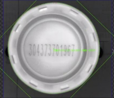
The cap image retains its marked digits and original vision overlays. Software menus have been cropped away.
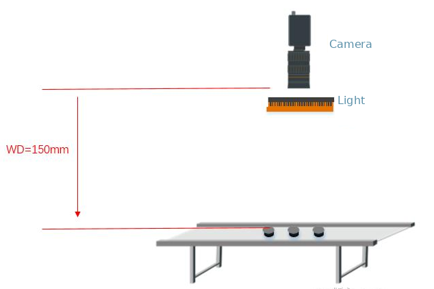
The drawing labels a 150 mm working distance for this arrangement. It is an application-specific reference, not a general installation requirement.
Select an image to view it at full size.
Read the digits and check the visible cap shape
A numerical marking and a circular cap outline support different inspection decisions. Reading the number does not establish that the cap is undamaged, and finding the contour does not establish that its number is correct. At changeover, the image settings and acceptance recipe must also match the cap currently presented.
For a digit-only task, assess a restricted OCR character set alongside a cap-reference locator and the required outline rule. In a HIKROBOT camera and VisionMaster arrangement, image acquisition settings and processing regions need to be qualified together. Different colours may share a recipe only when both marking contrast and edge evidence remain acceptable.
When is traditional OCR a sensible starting point?
Swipe across the table to compare all columns →
| Condition | Start by evaluating | What could change the choice |
|---|---|---|
| Digits only, stable font and consistent contrast | Traditional OCR using the restricted character set. | Weak strokes, merged digits or normal marking variation may reduce separation. |
| Cap moves or rotates in the image | Reliable localisation and alignment before character recognition. | An unstable reference or hidden marking may require imaging or handling changes. |
| Wide variation after the image has been improved | A trained recogniser compared on representative samples. | Training coverage, evaluation results and processing time determine suitability. |
| Code must match a production record | OCR plus a separate expected-value or format check. | Reading alone cannot enforce the correct job, sequence or batch rule. |
Compare processing methods using the same accepted marks, defects and complete timing budget. Reducing the acquired image can reduce data handling, but the chosen recogniser still needs to tolerate the validated marking variation. Neither traditional OCR nor a trained recogniser is automatically the best choice for every numerical mark.
Use the rule-based versus deep-learning guide to structure the comparison. Test difficult but acceptable markings as well as obvious defects. Keep the acceptance rules the same when comparing methods so a faster result is not obtained simply by relaxing the quality requirement.
Reduce the image region without losing the inspection
Reducing the acquired region before VisionMaster processes the frame can reduce data transfer and processing load. This differs from drawing a small OCR region inside a full image after acquisition. Confirm which image size reaches each stage and measure the effect while retaining the required cap movement and contour coverage.
Choose the region from the cap’s full permitted movement, not only its best-centred sample. Leave room for the outer contour if that same image must support the shape check. A crop that retains the digits but cuts off a displaced cap edge can make OCR faster while preventing a valid outline decision.
- 01Select the cap recipeConfirm the product colour and its approved imaging settings.
- 02Acquire the required regionKeep the marking and the necessary outline inside the image.
- 03Read and inspect separatelyCollect the digit result and the outer-contour result.
- 04Combine and communicateApply the specified release rules and track the result to the cap.
The setup drawing is a schematic rather than a measured installation photograph. Its camera, light and working-distance label explain the proposed geometry. The actual distance, lens choice and lighting need to preserve readable strokes and a usable edge across the permitted cap positions. See the camera and lens selection guide for the field-of-view trade-off.
Keep the outer-circle check within its useful scope
A visible outer-circle reference can support cap location and selected shape checks. Define the acceptance limit independently: perspective, normal moulding variation and cap tilt can change the apparent contour as well as actual damage.
Compare acceptable caps from the relevant variants with controlled deformation samples. Inspect the image and the matching result together before choosing a limit. A generic match score is not a dimensional tolerance; establish dimensional limits from the applicable drawing.
An outer contour also has limited coverage. It does not establish thread quality, liner presence, tamper-band strength or sealing performance. Use the broader closure inspection system scope when those defects matter; they may require other views or functional tests. Treat this case as a combined marking-and-visible-shape task.
Make colour changeover an imaging decision
Swipe across the table to compare all columns →
| Changeover question | What to test | Recipe decision |
|---|---|---|
| Can two colours share the image settings? | Mark contrast and cap-edge visibility under the same light and exposure. | Share a recipe only when both checks remain acceptable. |
| Does one colour need a different exposure or light setting? | The full marking and outline across its acceptable sample variation. | Store and identify the validated settings as a separate recipe. |
| Has the commanded recipe actually become active? | Product identity, recipe acknowledgement and the first cap result. | Define a hold or alarm when the requested and active states disagree. |
| What happens during restart or mixed-cap presentation? | The current cap against the active product and settings. | Prevent a previous product’s pass or parameter set from being reused silently. |
After a colour change, verify the requested and active recipe, exposure and illumination, cap-reference location, OCR expected values and outline limits together. A new exposure that improves the digits can still weaken the cap edge. Inspect an identified first-off sample and keep release on hold until the required checks are resolved.
A colour name alone is not enough to define a robust recipe. Surface finish, laser-mark contrast and normal material variation can also affect the image. Record which samples were accepted under each parameter set, then include the difficult variants in later changeover checks. The packaging changeover guide explains how expected product data and the active inspection job should stay aligned.
Worked example: better digits but an invalid cap edge
In an illustrative colour change, a brighter exposure makes the new marking readable but saturates part of the outer contour. OCR passes while shape inspection becomes unavailable. Keep the cap in hold and adjust the qualified lighting or exposure arrangement until both required regions are usable.
Confirm that the locator, acquired region and expected-number rule belong to the new recipe, then repeat first-off inspection with accepted and faulty caps. Preserve the recipe acknowledgement and both independent results. A pass from the previous colour must not complete a missing result under the new settings.
Measure the complete decision, not only one timing number
The plastics and packaging guide helps place cap marking and closure checks within the moulding, printing and packing workflow.
Measure trigger-to-result time over the qualified product and image variation. Include the slow or uncertain cases that require additional processing; one favourable algorithm timing is not a complete station budget.
Do not turn that algorithm time into a guaranteed conveyor throughput. Exposure, image transfer, processing, communication, product spacing and the time available before a physical reject all contribute to the station requirement. A cropped image may reduce some of those costs, but the effect must be measured on the selected hardware.
Swipe across the table to compare all columns →
| Validation sample or event | Evidence to collect |
|---|---|
| All digit patterns and difficult laser marks | Correct strings, no-reads and wrong reads assessed separately. |
| Accepted and deformed cap outlines | Shape result with the corresponding cap image and agreed criterion. |
| Each colour and its permitted surface variation | Performance under the intended recipe, including borderline acceptable marks. |
| Cap movement near the image boundary | Marking and required contour remain inside the acquired region. |
| Recipe switch, restart and missing result | Correct product association and a defined hold, reject or alarm response. |
| Normal and demanding line conditions | Processing-time distribution and complete trigger-to-result timing. |
For an assessment, provide the cap variants, marked character set, representative bad markings and deformation samples, the movement range and the timing available for a decision. The OCR/OCV inspection application helps define whether the requirement is reading, expected-content verification or both. If the problem is missing or displaced ink on a carton, the medicine carton date-code case provides a different validation pattern.
Scope and budget
Compare cap presentation, recipe changes and additional views with the closure inspection system scope and cost factors.
Testing and handover
Use the testing and handover process to agree changeover challenges for every cap colour and the response to unreadable marks.