Application guide by addaScanCompare the inspection task, imaging conditions and validation steps with your own production line.
- Inspection focus
- Splice position carried to the cutting station
- Primary theme
- Web inspection
- Decision evidence
- Pending web interval
- Trial priority
- Transparent and opaque tape
Connect the detected splice to material that must be isolated
The original English schematic explains the observable features and the proposed decision. The tables below set out the conditions to test on your own line.
Swipe across the diagram to see all details →
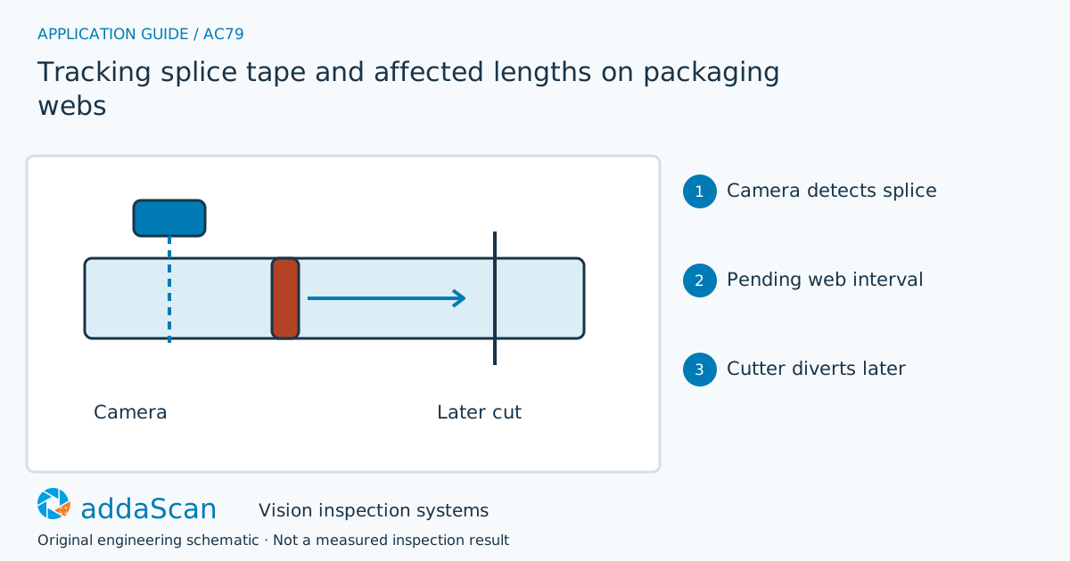
Detecting splice tape creates an outstanding material event. Its affected length must reach the containment point before that event can be closed. Original tracking schematic; reject length is process-specific.
Select an image to view it at full size.
Keep a roll-length event instead of a timed alarm
Tape appearance varies with colour, transparency and overlap. Use samples to define the visible splice region, then add only the containment allowance agreed for that process. The camera-to-cutter distance and encoder reference must be known. A fixed timer becomes unreliable when the web accelerates or stops; a length-based event still needs an explicit rule for slip, rewind and encoder loss.
Define the material reference at detection and the downstream point where affected product is isolated. The agreed affected length may extend beyond the visible tape, depending on the conversion process. Record that policy separately from the detector’s tape boundary so a recipe change does not silently alter which finished pieces are released.
Track travel in material coordinates using a qualified displacement reference. Wall-clock delay alone fails when the web stops or changes speed. Encoder slip, reverse travel and a changed path through a dancer or accumulator can also affect the relationship. Describe how the actual line preserves or invalidates the detected splice position through each of those conditions.
Compare a local alarm with downstream length tracking
Swipe across the table to compare all columns →
| Approach | Useful when | Limit or integration responsibility |
|---|---|---|
| Visual alarm only | Operator awareness | Does not identify which downstream pieces contain the splice. |
| Encoder-linked interval tracking | Automatic containment across speed changes | Requires verified distance, slip behaviour and reversal handling. |
A local splice alarm is sufficient only if the operator’s containment procedure can reliably identify the affected material. Automatic downstream diversion needs position tracking, conversion into piece or segment boundaries and confirmation of the physical action. Evaluate that full path instead of comparing tape detectors alone.
A stopped web still contains an outstanding splice
Illustrative scenario: a splice has crossed the camera but is still upstream of the cutter. Do not reject the unrelated piece currently at discharge.
Keep the affected interval pending until its material position reaches the handling point. If the web reverses or pulses are lost, freeze unresolved events and reconcile the roll reference. Release unaffected production only once the containment interval can again be placed confidently; retain the diverted piece range.
On rewind or lost position, mark the affected interval unresolved and use a controlled containment boundary or new reference. Do not continue the queued reject from a position that is no longer known. Preserve splices detected before a stop until their material has been accounted for.
Challenge tape appearance and lost material position
Swipe across the table to compare all columns →
| Challenge sample or event | Expected behaviour to establish | Evidence to retain |
|---|---|---|
| Transparent and opaque tape | Save detected boundaries against known splice locations. | Tape/material sample, detected splice start/end, roll identity and the approved additional affected-length policy. |
| Stop with splice between stations | Divert the correct later pieces after restart. | Position at stop, splice queue, displacement after restart and the actual downstream segment isolated. |
| Rewind or lost pulses | Hold unresolved intervals until position is reconciled. | Reverse travel or pulse-loss record, uncertainty boundary, position re-establishment and containment disposition. |
Test transparent and opaque tape at permitted positions, then stop with the splice between stations. Challenge restart, rewind and loss of displacement. Confirm the isolated pieces against their material positions, not only the electrical reject pulse.
Splice detection does not define the reject length by itself
Splice visibility does not establish joint strength. Containment allowances come from the process specification.
Map the distance from inspection to containment
Share permitted photos or drawings, plus details of tape types, web paths, cutter pitch, station distances and rewind behaviour. Agree any physical sample arrangements after the initial assessment.
Web and line-scan inspection covers continuous-material acquisition and tracking. Include the path to the cutter or discharge and the response to lost position in the scope.
Transparent film defect inspection detects film defects. Both defect and splice containment require the right material segment to be tracked to the downstream action.
Use the cost and scope guide to understand the station boundary. Include material-position tracking, downstream containment and any line-scan hardware in the separate web-system scope.
For line conditions around splice position carried to the cutting station, see plastics and packaging inspection.
Compare lighting, processing, interfaces and support in the HIKROBOT and other vision solutions guide. Agree sample testing, acceptance responsibilities and handover through the delivery process.